TM-9-2320-272-23-5 - Page 329 of 623
AIR DRYER REMOVAL
WARNING
Do not disconnect air lines before draining air reservoirs. Small parts under pressure may
shoot out with high velocity. Failure to comply may result in injury or death to personnel.
CAUTION
When disconnecting air lines and hoses, plug all openings to prevent dirt from entering and
causing damage to internal parts. Remove all plugs prior to installation.
NOTE
•
Tag lines and fittings for installation.
•
Mark fitting direction for installation.
•
M939/A1/A2 air dryer assemblies are mounted on frame crossmember under vehicle and
M936 wrecker air dryer assemblies are mounted on outside of passenger side frame rail
behind fuel tank.
1.
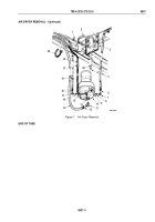
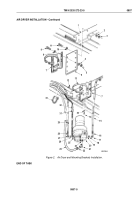
Remove two tiedown straps (Figure 1, Item 23) and disconnect air dryer heater connector (Figure 1, Item 21)
from ABS wiring connector (Figure 1, Item 22). Discard tiedown straps.
2.
Loosen nut (Figure 1, Item 6) and remove air inlet supply line (Figure 1, Item 5) from elbow (Figure 1, Item 7)
on side of air dryer housing (Figure 1, Item 10).
3.
Loosen nut (Figure 1, Item 12) and remove air outlet supply line (Figure 1, Item 14) from elbow
(Figure
1,
Item 11) on bottom of air dryer housing (Figure 1, Item 10).
4.
Loosen nut (Figure 1, Item 18) and remove governor air supply line (Figure 1, Item 19) from elbow
(Figure
1,
Item
17) on side of air dryer housing (Figure 1, Item 10).
5.
Remove nut (Figure 1, Item 1), clamp (Figure 1, Item 2), and air dryer housing (Figure 1, Item 10) from air
dryer support bracket (Figure 1, Item 3).
6.
Remove screw (Figure 1, Item 4) and lockwasher (Figure 1, Item 20) from bottom of air dryer housing
(Figure
1, Item 10) and air dryer support bracket (Figure 1, Item 3). Discard lockwasher.
7.
Remove elbow (Figure 1, Item 7) and adapter (Figure 1, Item 8) from inlet port (Figure 1, Item 9) on side of air
dryer housing (Figure 1, Item 10).
8.
Remove elbow (Figure 1, Item 17) and adapter (Figure 1, Item 16) from governor control port
(Figure
1,
Item
15) on side of air dryer housing (Figure
1, Item 10).
9.
Remove elbow (Figure 1, Item 11) from outlet port (Figure 1, Item 13) on bottom of air dryer housing
(Figure
1,
Item
10).
TM 9-2320-272-23-5
0807
0807-2
Back to Top

