TM-9-2320-272-24-1 - Page 414 of 1015
TM 9-2320-272-24-1
3-14. AIR CLEANER INTAKE PIPE (M939/A1) MAINTENANCE
THIS TASK COVERS:
a. Removal
b. Inspection
c. Installation
INITIAL SETUP:
APPLICABLE MODELS
REFERENCES (TM)
M939/A1
TM 9-2320-272-10
TOOLS
TM 9-2320-272-24P
General mechanic’s tool kit (Appendix E, Item 1)
EQUIPMENT CONDITION
MATERIALS/PARTS
l
Parking brake set (TM 9-2320-272-10).
l
Hood raised and secured (TM 9-2320-272-10).
Three locknuts (Appendix D, Item 288)
l
Left splash shield removed (TM 9-2320-272-10).
l
Ether valve and bracket removed (para. 3-35).
a. Removal
1.
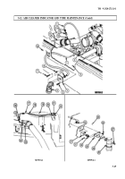
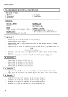
Remove locknut (9), air intake clamp (15), screw (6), and harness cable clamp (7) from hanger
strap (8). Discard locknut (9).
2.
Loosen hose clamps (13) and (5) and remove air intake pipe (14) and hose clamps (13) and (5) from
lower hump hose (12) and upper hump hose (4).
3.
Loosen hose clamp (3) and remove upper hump hose (4) and hose clamp (3) from air intake
manifold (2).
4.
Loosen hose clamp (11) and remove lower hump hose (12) and hose clamp (11) from air cleaner (10).
5.
Remove locknut (22), washer (23), hanger strap (8), and screw (19) from mounting bracket (20).
Discard locknut (22).
NOTE
Assistant will help with step 6.
6.
Pull back floor mat (17) in cab (1), and remove locknut (21), mounting bracket (20), and screw (16)
from floor (18). Discard locknut (21).
7.
Remove intake clamp (15) from intake pipe (14).
b. Inspection
Inspect upper and lower hump hoses (4) and (12) and intake pipe (14) for cracks. Replace if cracked.
c. Installation
1.
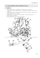
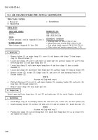
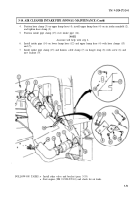
Install hanger strap (8) on mounting bracket (20) with screw (19), washer (23), and new locknut (22).
2.
Install mounting bracket (20) on floor (18) with screw (16) and new locknut (21). Install floor mat (17).
NOTE
Assistant will help with step 3.
3.
Position hose clamp (11) on lower hump hose (12), install lower hump hose (12) on air cleaner (10),
and tighten hose clamp (11).
3-50
Back to Top

