TM-9-2320-272-24-1 - Page 406 of 1015
TM 9-2320-272-24-1
3-12. AIR CLEANER INDICATOR AND TUBE MAINTENANCE
THIS TASK COVERS:
a. Testing
c. Cleaning and Inspection
b. Removal
d. Installation
INITIAL SETUP:
APPLICABLE MODELS
All
TOOLS
General mechanic’s tool kit (Appendix E, Item 1)
MATERIALS/PARTS
Two locknuts (Appendix D, Item 313)
Antiseize tape (Appendix C, Item 72)
REFERENCES (TM)
EQUIPMENT CONDITION
l
Parking brake set (TM 9-2320-272-10).
l
Hood raised and secured (TM 9-2320-272-10).
l
Left splash shield removed (TM 9-2320-272-10).
GENERAL SAFETY INSTRUCTIONS
When cleaning with compressed air, wear eyeshields
and ensure source pressure does not exceed 30 psi
(207 kPa).
TM 9-2320-272-10
TM 9-2320-272-24P
1.
2.
3.
4.
5.
6.
NOTE
Perform step 1 for M939/A1 series vehicles.
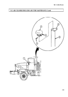
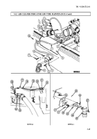
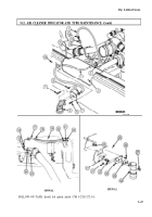
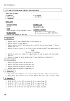
Remove nut (3), screw (6), and extension tube cap (2) from extension tube (5).
Start engine (TM 9-2320-272-10) and run at 1,200 rpm.
Cover 90 percent of intake extension tube (5) opening with cardboard (4).
Observe filter indicator (1) to ensure red band is visible. If red band is visible, indicator (1) works
properly. If not, replace indicator (1).
Remove cardboard (4) and reset indicator (1) (TM 9-2320-272-10) if working properly.
NOTE
Perform step 6 for M939/A1 series vehicles.
Install extension tube cap (2) on extension tube (5) with screw (6) and nut (3).
3-42
Back to Top

