TM-9-2320-272-24-1 - Page 396 of 1015
3-7. OIL
TM 9-2320-272-24-1
THIS TASK COVERS:
a. Removal
b. Inspection
c. Installation
INITIAL SETUP:
APPLICABLE MODELS
M939/A1
REFERENCES (TM)
LO 9-2320-272-12
TM 9-2320-272-10
TOOLS
TM 9-2320-272-24P
General mechanic’s tool kit (Appendix E, Item 1)
Torque wrench (Appendix E, Item 146)
MATERIALS/PARTS
Antiseize tape (Appendix C, Item 72)
EQUIPMENT CONDITION
Parking brake set (TM 9-2320-272-10).
Hood raised and secured (TM 9-2320-272-10).
Left splash shield removed (TM 9-2320-272-10).
Engine oil drained (para. 3-5).
NOTE
Engine oil pan is mounted with screw-assembled washers on
late model engines.
Have adequate drainage container ready to catch oil.
1.
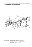
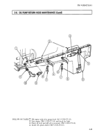
Remove two screws (6), washers (7), and clamps (5) from oil pump pickup and return hoses (2) and (8)
and engine oil pan (3).
2.
Disconnect oil pump pickup hose (2) from adapter flange (4) and oil pump (1).
Inspect oil pump pickup hose (2). Replace if threads are stripped or hose (2) is cracked or frayed.
1.
Apply antiseize tape to male pipe threads of oil pump pickup hose (2) and adapter flange (4).
2.
Connect oil pump pickup hose (2) to oil pump (1) and adapter flange (4).
3.
Install two clamps (5) on oil pump pickup and return hoses (2) and (8) and engine oil pan (3) with
two washers (7) and screws (6). Tighten screws (6) 35-40 lb-ft (47-54 N•m).
3-32
Back to Top

