TM-9-2320-272-24-1 - Page 448 of 1015
TM 9-2320-272-24-1
3-27. FUEL TANK (M936/A1/A2) MAINTENANCE
THIS TASK COVERS:
a. Draining
b. Removal
c. Inspection
d. Installation
INITIAL SETUP:
APPLICABLE MODELS
M936/A1/A2
TOOLS
General mechanic’s tool kit (Appendix E, Item 1)
MATERIALS/PARTS
Two lockwashers (Appendix D, Item 358)
Gasket (Appendix D, Item 144)
Gasket (Appendix D, Item 143)
Gasket (Appendix D, Item 142)
Locknut (Appendix D, Item 299)
Three locknuts (Appendix D, Item 288)
Lockwasher (Appendix D, Item 379)
Antiseize tape (Appendix C, Item 72)
REFERENCES (TM)
FM 43-2
TM 9-2320-272-10
TM 9-2320-272-24P
EQUIPMENT CONDITION
Parking brake set (TM 9-2320-272-10).
GENERAL SAFETY INSTRUCTIONS
Diesel fuel is flammable. Do not perform this
procedure near flames.
WARNING
Diesel fuel is highly flammable. Do not perform fuel system
procedures near open flame. Injury to personnel may result.
NOTE
The replacement procedure for right and left fuel tanks is basically
the same. This procedure covers the left fuel tank.
1.
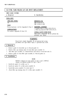
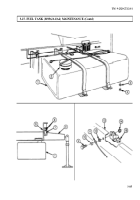
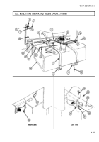
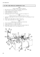
Loosen fuel filler cap (2) at top of tank (1).
NOTE
Have drainage container ready to catch fuel.
2.
Remove drainplug (4) and gasket (3) from bottom of fuel tank (1). Discard gasket (3).
3.
After draining is complete, install new gasket (3) and drainplug (4) in fuel tank (1).
4.
Tighten fuel filler cap (2) on fuel tank (1).
b. Removal
1.
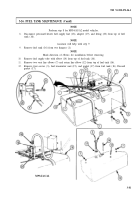
Loosen two nuts on screws (6) on wrecker body (5), and slide stop plate (7) upward.
2.
Remove outrigger (8) from body (5).
3.
Remove locknut (14), screw (9), washer (10), ground wire (11), and lockwasher (12) from left side of
frame (13) and double check valve (15). Discard locknut (14) and lockwasher (12).
3-84
Back to Top

