TM-9-2320-272-24-1 - Page 488 of 1015
TM 9-2320-272-24-1
3-42. ACCELERATOR LINKAGE (M939/A1) MAINTENANCE
THIS TASK COVERS:
a. Removal
b. Installation
c. Adjustment
APPLICABLE MODELS
REFERENCES (TM)
M939/A1
TM 9-2320-272-10
TOOLS
TM 9-2320-272-24P
General mechanic’s tool kit (Appendix E, Item 1)
EQUIPMENT CONDITION
MATERALS/PARTS
l
Parking brake set (TM 9-2320-272-10).
l
Hood raised and secured (TM 9-2329-272-10).
Locknut (Appendix D, Item 276)
Locknut (Appendix D, Item 277)
Screw (Appendix D, Item 569)
Spring pin (Appendix D, Item 674)
l
Left splash shield removed (TM 9-2320-272-10).
1.
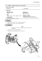
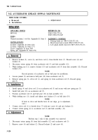
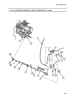
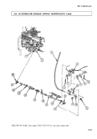
Remove locknut (2), screw (6), and clevis rod (1) from throttle lever (7). Discard screw (6) and
locknut (2).
2.
Disconnect return spring (8) from accelerator rod (5) and link assembly (12).
3.
While holding nut (11), remove locknut (13) and accelerator rod (5) from link assembly (12). Discard
locknut (13).
NOTE
Record position of accelerator rod in ball joint for installation.
4.
Loosen jamnut (9) and remove ball joint (10) from accelerator rod (5).
6.
Remove spring pin (3), clevis rod (1), and spring (4) from accelerator rod (5). Discard spring
pin (3).
1.
Install spring (4) and clevis rod (1) on accelerator rod (5) and secure with new spring pin (3).
2.
Install ball joint (10) on accelerator rod (5).
3.
Position accelerator rod (5) and ball joint (10) on link assembly (12).
4.
While holding nut (11), install and tighten new locknut (13) on ball joint (10).
NOTE
If hole in clevis and throttle lever do not align, go to adjustment,
task c.
5.
Connect clevis rod (1) to throttle lever (7) with new screw (6) and new locknut (2).
6.
Connect return spring (8) to accelerator rod (5) and link assembly (12).
NOTE
Perform step 1 only if link assembly was removed.
1.
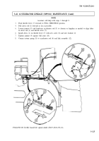
Disconnect return spring (8) from link assembly (12) and accelerator rod (5).
2.
Remove screw (6) and locknut (2). Discard locknut (2) and screw (6).
3-124
Back to Top

