TM-9-2320-272-24-1 - Page 490 of 1015
TM 9-2320-272-24-1
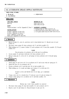
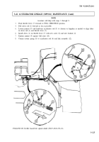
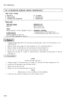
3-43. ACCELERATOR LINKAGE (M939A2) MAINTENANCE
THIS TASK COVERS:
a. Removal
b. Disassembly
c. Cleaning and Inspection
d. Assembly
e. Installation
f. Adjustment
INITIAL SETUP:
APPLICABLE MODELS
M939A2
TOOLS
REFERENCES (TM)
TM 9-2320-272-10
TM 9-2320-272-24P
General mechanic’s tool kit (Appendix E, Item 1)
EQUIPMENT CONDITION
MATERlALS/PARTS
l
Parking brake set (TM 9-2320-272-10.
l
Hood raised and secured (TM 9-2320-272-10).
Locknut (Appendix D, Item 277)
Two cotter pins (Appendix D. Item 46)
1.
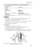
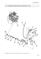
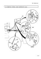
Compress spring-loaded sleeve (22) and remove quick-disconnect socket (21) from ball joint (1) on
control lever (2).
2.
Remove throttle return spring (14) from accelerator rod (15) and throttle shaft (6).
3.
Remove locknut (9) and ball joint (12) from bracket (8). Discard locknut (9).
4.
Loosen screw (11) and remove connector (10) and cable (3) from bracket (8).
5.
Remove two cotter pins (5), washers (7), throttle shaft (61, and bracket (8) from bracket (4). Discard
cotter pins (5).
b. Disassembly
1.
2.
3.
4.
5.
NOTE
Assistant will help with step 1.
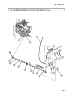
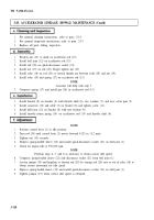
Compress spring (17) and remove pin (16), spring (17), and yoke (18) from accelerator rod (15).
Loosen nut (19) and remove yoke (18) from rod (20).
Remove nut (19) from rod (20).
Remove rod (20) from quick-disconnect socket (211.
NOTE
Mark position of nut on accelerator rod for installation.
Loosen nut (13) and remove ball joint (12) from accelerator rod (15).
3-126
Back to Top

