TM-9-2320-272-24-1 - Page 494 of 1015
TM 9-2320-272-24-1
3-44. EMERGENCY STOP CONTROL CABLE MAINTENANCE
THIS TASK COVERS:
a. Removal
b. Inspection
c. Installation
INITIAL SETUP:
APPLICABLE MODELS
All
TOOLS
General mechanic’s tool kit (Appendix E, Item 1)
EQUIPMENT CONDITION
MATERIALS/PARTS
Locknut (M939/A1) (Appendix D, Item 313)
Lockwasher (M939/A1) (Appendix D, Item 381)
Lockwasher (Appendix D, Item 354)
Lockpin (M939A2) (Appendix D, Item 271)
GAA grease (Appendix C, Item 28)
1.
2.
3.
4.
5.
6.
7.
8.
9.
10.
11.
12.
13.
REFERENCES (TM)
TM 9-2320-272-10
TM 9-2320-272-24P
l
Parking brake set (TM 9-2320-272-10).
l
Hood raised and secured (TM 9-2320-272-10).
l
Battery ground cables disconnected (para. 3-126).
l
Left splash shield removed (TM 9-2320-272-10).
NOTE
Steps 1 through 4 are for M939A2 series vehicles.
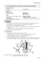
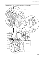
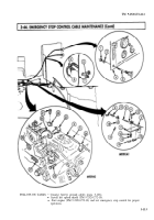
Remove lockpin (10), washer (11), and cable pivot (4) from shutoff valve lever (1). Discard
lockpin (10).
Remove screw (2), connector (3), and cable pivot (4) from cable (5).
Remove screw (9), clamp (7), and cable conduit (6) from fuel bracket (8).
Remove clamp (7) from conduit (6).
NOTE
Steps 5 through 9 are for M939/A1 series vehicles.
Remove connector screw (18) and connector (19) from shutoff valve control lever (28) and cable (5).
Remove connector (19) from stop control cable (5).
Remove locknut (24), washer (25), and screw (21) from clamp (20) on conduit (6) and conduit clamp
bracket (26). Discard locknut (24).
Remove screw (23), lockwasher (22), and clamp bracket (26) from engine (27). Discard lockwasher (22).
Remove clamp (20) from conduit (6).
NOTE
Steps 10 through 13 applies to all vehicles.
From behind instrument panel (15), remove nut (12) and lockwasher (13) on emergency stop
control (14). Discard lockwasher (13).
Pull emergency stop control (14), conduit (6), and cable (5) through firewall (17), grommet (16), and
instrument panel (151.
Remove grommet (16) from tirewall (17).
NOTE
Perform step 13 only if replacing stop control cable.
Remove stop control cable (5) and handle of stop control (14) from conduit (6).
3-130
Back to Top

