TM-9-2320-272-24-1 - Page 554 of 1015
3-65. THERMOSTAT
TM 9-2320-272-24-1
THIS TASK COVERS:
a. Removal
b. Testing
c. Installation
INITIAL SETUP:
APPLICABLE MODELS
REFERENCES (TM)
M939/A1
TM 9-2320-272-10
TOOLS
TM 9-2320-272-24P
General mechanic’s tool kit (Appendix E, Item 1)
EQUIPMENT CONDITION
Hot water thermometer
• Hood raised and secured (TM 9-2320-272-10).
MATERIALS/PARTS
• Parking brake set (TM 9-2320-272-10).
• Right splash shield removed (TM 9-2320-272-10).
Four screw-assembled lockwashers (Appendix D,
Item 592)
• Cooling system drained as necessary (para. 3-53).
Gasket (Appendix D, Item 147)
GENERAL SAFETY INSTRUCTIONS
Thermostat seal (Appendix D, Item 597)
GAA grease (Appendix C, Item 28)
Use caution when testing thermostat. Scalding hot
water may cause severe burns.
1.
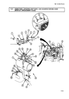
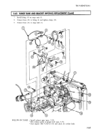
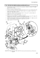
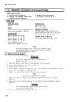
Loosen clamp (6) and disconnect radiator inlet hose (7) from thermostat housing (5).
2.
Loosen two clamps (9) and remove radiator bypass hose (10) from thermostat housing (5) and
radiator bypass tube (8).
3.
Remove four screw-assembled lockwashers (11) from thermostat housing (5) and water manifold
header (1). Discard screw-assembled lockwashers (11).
4.
Remove thermostat housing (5) and gasket (2) from water manifold header (1). Discard gasket (2)
and clean gasket remains from mating surfaces.
5.
Remove thermostat (3) from thermostat housing (5).
6.
Remove seal (4) from thermostat housing (5). Discard seal (4).
WARNING
Use caution when testing thermostat. Hot water may cause injury
to personnel.
1.
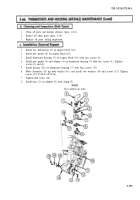
Place thermostat (3) in a container of water at 197°F (92°C).
NOTE
Do not let thermostat touch container sides during testing.
2.
Observe thermostat (3) to see if valve opens. Replace thermostat (3) if valve does not fully open.
1.
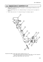
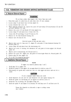
Position new seal (4) in thermostat housing (5).
2.
Install thermostat (3) in thermostat housing (5).
3.
Coat one surface of gasket (2) with light coat of GAA grease and position new gasket (2) over four
holes on water manifold header (1).
3-190
Back to Top

