TM-9-2320-272-24-2 - Page 20 of 991
TM 9-2320-272-24-2
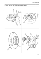
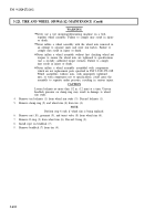
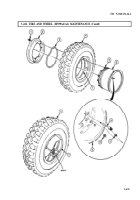
Inspect rim (5) and tire lockring (2) for bends, cracks, breaks, distortion, or pitting from corrosion.
Replace rim (5) and tire lockring (2) if bent, cracked, broken, distorted, or pitted.
1.
Install inner tube (6) and tire liner (9) inside tire (3).
2.
Install valve core (7) on inner tube valve stem (4).
3.
Inflate inner tube (6) just enough to prevent puncture when wheel (1) is installed.
4.
Place wheel (1) on the ground, rim (5) side down.
Lockring must be properly seated around wheel when installed.
If lockring is not correctly installed, it may explode off when tire
is inflated, causing injury to personnel.
Never attempt to correct seating of lockring by hammering,
striking, or forcing while tire is inflated. Lockring may explode
off, causing injury to personnel.
5.
Install tire (3) over wheel (1) and guide stem (4) through hole in wheel (1).
6.
Force lockring (2) onto wheel (1), opposite rim (5).
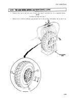
Always use a tire inflation cage for inflation purposes. Stand on
one side of cage during inflation; never directly in front. Keep
hands out of cage during inflation. Inflate assembly to
recommended pressure, using a clip-on air chuck. Do not exceed
cold inflation pressure. See vehicle operator’s manual for
recommended tire pressure. Failure to do so may result in injury
to personnel.
7.
Inflate tire (3) to proper pressure (TM 9-2320-272-10).
8.
Observe lockring (2) for proper seating on wheel (1).
9.
Install valve cap (8) on inner tube valve stem (4).
10.
Inspect rim (5) and lockring (2) for proper seating and locking while tire (3) is still in inflation cage.
11.
If lockring (2) adjustment is required, deflate tire (3) completely before adjusting.
3-628
Back to Top

