TM-9-2320-272-24-2 - Page 438 of 991
3-414. A-FRAME
TM 9-2320-272-24-2
THIS TASK COVERS:
a. Removal
b. Inspection
c. Installation
INITIAL SETUP:
APPLICABLE MODELS
EQUIPMENT CONDITION
M925/A1/A2, M928/A1/A2, M932/A1/A2
•
•
TOOLS
General mechanic’s tool kit (Appendix E, Item 1)
•
MATERIALS/PARTS
Lockwasher (Appendix D, Item 416)
•
•
PERSONNEL REQUIRED
Parking brake set (TM 9-2320-272-10).
Cab tarpaulin removed (task c. only)
(TM 9-2320-272-10).
Windshield lowered (task c. only)
(TM 9-2320-272-10).
Tailgate removed (except M932/A1/A2)
(task c. only) (para. 3-343).
Front lifting shackles removed (task c. only)
(para. 3-241).
TWO
REFERENCES (TM)
TM 9-2320-272-10
TM 9-2320-272-24P
GENERAL SAFETY INSTRUCTION
Do not perform this procedure near high-voltage wires.
Do not perform this procedure near high-voltage wires. Vehicle
will become charged with electricity if A-frame contacts or breaks
high-voltage wire. Do not leave vehicle while high-voltage line is
in contact with A-frame or vehicle. Failure to comply may result in
injury to personnel.
1.
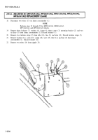
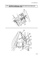
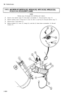
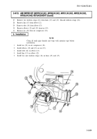
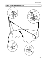
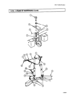
Remove snatch block (2) from A-frame spreader tube (1).
2.
Remove setscrew (10) from each A-frame leg (9) and bracket (11).
NOTE
Assistant will push A-frame toward cab during steps 3 and 4.
3.
Remove shackle pin (7) from shackle (6) and separate cable (3) and harness (8) from shackle (6).
4.
Remove cable (3) from pintle hook (5) and eyebolt (4).
3-1046
Back to Top

