TM-9-2320-272-24-3 - Page 462 of 799
TM 9-2320-272-24-3
4-144. DUMP BODY MAINTENANCE
THIS TASK COVERS:
a.
Removal
b.
Inspection and Repair
c. Installation
INITIAL SETUP:
APPLICABLE MODELS
M929/A1/A2, M930/A1/A2
TOOLS
General mechanic’s tool kit (Appendix E, Item 1)
Torque wrench (Appendix E, Item 145)
Two utility chains
Lifting device
Shop stands
MATERIALS/PARTS
Locknut (Appendix D, Item 309)
Six locknuts (Appendix D, Item 321)
Locknut (Appendix D, Item 291)
PERSONNEL REQUIRED
Three
MANUAL REFERENCES (TM)
LO 9-2320-272-12
TM 43-0139
TM 9-2320-272-10
TM 9-2320-272-24P
EQUIPMENT CONDITION
l
Parking brake set (TM 9-2320-272-10).
l
Wheels chocked (TM 9-2320-272-10).
GENERAL SAFETY INSTRUCTIONS
l
Position safety braces before working under raised
dump body.
l
Do not operate dump controls when dump body is
removed.
l
All personnel must stand clear during lifting
operations.
l
Lifting device must have a capacity greater than
the weight of the dump body.
WARNING
l
Lifting device must have a weight capacity greater than the
combined weight of the dump body to prevent injury or death to
personnel and damage to equipment.
l
All personnel must stand clear during lifting operations. A
snapped cable, or swinging or shifting load, may result in injury
or death to personnel.
l
Never work under dump body until safety braces are properly
positioned. Injury to personnel may result if dump body
suddenly lowers.
1.
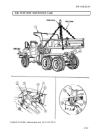
Place dump body (1) in raised position (TM 9-2320-272-10).
2.
Place safety braces (6) in proper position (TM 9-2320-272-10).
NOTE
Step 3 applies to both left and right thrust plates.
3.
Remove locknut (3) and screw (5) from thrust plate (2) and thrust plate pin (4). Discard locknut (3).
4.
Remove safety braces (6) and place dump body (1) in lowest position (TM 9-2320-272-10).
5.
Wrap two utility chains around subframe beam (9) and fasten hooks over utility chains.
6.
Attach lifting device to center of utility chains.
7.
Raise lifting device until slack is removed from chains.
4-726
Back to Top


