TM-9-2320-272-24-3 - Page 470 of 799
TM 9-2320-272-24-3
4-147. DUMP BODY HYDRAULIC HOSE REPLACEMENT
THIS TASK COVERS:
a.
Removal
b. Installation
INITIAL SETUP:
APPLICABLE MODELS
M929/A1/A2, M930/A1/A2
TOOLS
General mechanic’s tool kit (Appendix E, Item 1)
MATERIALS/PARTS
Cap and plug set (Appendix C, Item 14)
MANUAL REFERENCES (TM)
LO 9-2320-272-12
TM 9-2320-272-10
TM 9-2320-272-24P
EQUIPMENT CONDITION
l
Parking brake set (TM 9-2320-272-10).
l
Dump body in lowered position (TM 9-2320-272-10).
l
Hydraulic oil reservoir drained (LO 9-2320-272-12).
GENERAL SAFETY INSTRUCTIONS
l
Position safety braces before working under raised
dump body.
l
Ensure dump control lever is in the NEUTRAL
position and has not moved.
l
Store or dispose of used oil properly.
l
Do not remove lines when engine is running or
start engine when lines are removed.
l
Never work under dump body until safety braces are properly
positioned. Injury to personnel may result if dump body
suddenly lowers.
l
Ensure dump control lever is in the NEUTRAL position and has
not moved. Injury to personnel may result if lift cylinder is
operated when not secured.
l
Accidental or intentional introduction of liquid contaminants
into the environment is in violation of state, federal, and
military regulations. Refer to Army POL (para. 1-8) for
information concerning storage, use, and disposal of these
liquids. Failure to do so may result in injury or death.
l
Do not remove hoses with engine running or start engine with
hoses removed. High-pressure fluids may cause hoses to whip
violently and spray randomly. Doing so may result in injury to
personnel.
NOTE
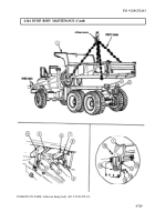
All hydraulic hoses are removed the same way This procedure
covers dump hoist cylinder and safety lock hoses only.
1.
Place dump body in raised position (TM 9-2320-272-10).
2.
Place safety braces in proper position (TM 9-2320-272-10).
CAUTION
Plug all hydraulic lines or openings to prevent dirt from entering
and damaging components.
4-734
Back to Top

