TM-9-2320-272-24-3 - Page 478 of 799
TM 9-2320-272-24-3
4-149. DUMP SUBFRAME REPLACEMENT
THIS TASK COVERS:
a.
Removal
b.
Installation
INITIAL SETUP:
APPLICABLE MODELS
M929/A1/A2, M930/A1/A2
TOOLS
General mechanic’s tool kit (Appendix E, Item 1)
MATERIALS/PARTS
Eight locknuts (Appendix D, Item 321)
Four cotter pins (Appendix D, Item 69)
Cap and plug set (Appendix C, Item 14)
PERSONNEL REWIRED
Three
MANUAL REFERENCES (TM)
LO 9-2320-272-12
TM 9-2320-272-10
TM 9-2320-272-24P
EQUIPMENT CONDITION
l
Parking brake set (TM 9-2320-272-10).
l
Hydraulic oil reservoir drained (LO 9-2320-272-12).
l
Dump body removed (para. 4-144).
GENERAL SAFETY INSTRUCTIONS
l
Store or dispose of used oil properly.
l
Do not remove lines when engine is running or
start engine when lines are removed.
l
All personnel must stand clear during lifting
operations.
WARNING
l
Accidental or intentional introduction of liquid contaminants
into the environment is in violation of state, federal, and
military regulations. Refer to Army POL (para. 1-8) for
information concerning storage, use, and disposal of these
liquids. Failure to do so may result in injury or death.
l
Do not remove hoses with engine running or start engine with
hoses removed. High-pressure fluids may cause hoses to whip
violently and spray randomly. Doing so may result in injury to
personnel.
CAUTION
Plug all hydraulic lines or openings to prevent dirt from entering
and damaging components.
NOTE
l
Have container ready to catch oil from hydraulic tubes, lines,
and hoses.
l
Drain hoses before plugging.
l
Tag hoses for installation.
1.
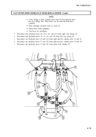
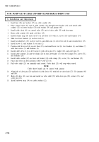
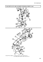
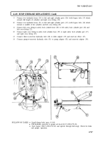
Disconnect pump-to-reservoir hydraulic tube (2) from pump adapter (3) and reservoir adapter (1).
2.
Disconnect filter-to-reservoir hydraulic hose (5) from filter elbow (4) and reservoir adapter (6).
4-742
Back to Top

