TM-9-2320-272-24-3 - Page 608 of 799
4-181. REAR
TM 9-2320-272-24-3
1.
2.
3.
4.
5.
6.
7.
8.
9.
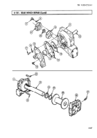
Position end cover (10) on shaft (6), ensuring tabs of thrust washer (11) engage slots in end cover (10).
Measure clearance between gearcase (3) and cover (10) with feeler gauge.
a.
b.
If there is zero clearance, remove cover (10) and install gasket (12) and cover (10) on gearcase (3)
(step c.).
C.
If a measurable gap, add one to four gaskets (12) and remeasure gap. Allowable gap is 0.005-
0.015 in. (0.13-0.38 mm).
When proper clearance is obtained, remove cover (10) and gasket(s) (12), coat gasket(s) (12) with
sealing compound, and install gasket(s) (12) and cover (10) on gearcase (3) with two screws (14)
and six new lockwashers (9) and screws (8).
NOTE
Apply a light film of oil to all parts during assembly. Do not
lubricate brake band or brake drum.
Place worm shaft (4) and worm gear (5) in gearcase (3) with keyway end of worm shaft (4) at mating
mark side of gearcase (3). Let worm gear (5) rest on rag in gearcase (3).
Coat thrust washer (2) with light coat of GAA grease and slide over long end of drum shaft (6).
Ensure locking tab on thrust washer (2) points toward long end of drum shaft (6).
Install drum shaft (6) and gear (7) part way through bushing (13) in gearcase (3) and position tab of
thrust washer (2) into notch in gearcase (3)
Complete installation of drum shaft (6) and gear (7) into gearcase (3) until gear (7) is seated on
thrust washer (2).
Position worm gear shaft (4) in gearcase (3), ensuring worm gear (5) is engaging drum shaft gear (7).
Coat thrust washer (1) with coat of GAA grease and place over shaft (6) with tabs pointing away
from drum shaft gear (7).
Install bushing (13) in end cover (10).
NOTE
Do not install gasket at this time.
4-872
Back to Top


