TM-9-2320-272-24-4 - Page 112 of 836
TM 9-2320-272-24-4
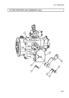
5-18. FUEL PUMP SETUP AND CALIBRATION (Contd)
b. Mounting Pump to Test Stand
1.
2.
3.
4.
5.
6.
7.
8.
9.
10.
11.
12.
13.
14.
15.
16.
17.
18.
Install adapter ring (7) on adapter bracket (8) with four washers (9) and screws (6). Ensure the
word TOP or part number on adapter ring (7) faces up.
Install ring and adapter bracket (4) on mounting rails (16) of test stand with clamp bar (14).
Tighten clamp bar (14) finger tight.
Mount fuel pump (11) to ring and adapter bracket (4) with four screws (12) and washers (13).
Place pump coupling insert (15) into test stand drive coupling (10).
Loosen clamp bar (14) and slide fuel pump (11) and ring and adapter bracket (4) forward to engage
drive coupling (10).
NOTE
Clean all male pipe threads and wrap with sealing tape before
installation.
Install inlet adapter (27) on pump elbow (26).
Connect 1/2 in. (12.7 mm) flexible hose (30) from test stand fuel pressure control valve (32) to
adapter (27).
Connect 1/4 in. (6.35 mm) manifold hose (24) from manifold vacuum adapter (28) to adapter (21).
Install pump discharge fitting (18) in fuel pump shutoff solenoid valve (19).
Install fuel pressure hose (17) from test stand pressure gauge outlet (38) to pump discharge fitting (18).
Install 1/2 in. (12.7 mm) flexible hose (25) from test stand lube pressure (31) to test stand lube
return (22).
Install fuel input hose (37) from test stand fuel input connector (36) to pump discharge fitting (18).
Install fuel outlet hose (33) from test stand fuel outlet connector (34) to test stand fuel return
connector (23).
Install leakage accumulator hose (40) to No. 1 accumulator can (41) from test stand leak test
connector (39).
Connect 1/4 in. (6.35 mm) flexible hose (29) to check valve fitting (20) on fuel pump (11) and to
auxiliary return connector (35).
Install throttle lever position holding spring (1) from top of throttle shaft lever (3) to ring and
adapter bracket (4). Spring (1) will hold throttle shaft lever (3) to full fuel position.
Remove governor spring pack housing pipe plug (2) from spring pack housing (5).
Install spring pack adjusting tool into spring pack housing (5).
5-106
Back to Top


