TM-9-2320-272-24-4 - Page 106 of 836
TM 9-2320-272-24-4
5-16. THROTTLE COVER AND SHAFT MAINTENANCE (Contd)
c. Assembly
1.
2.
3.
4.
5.
6.
7.
8.
9.
NOTE
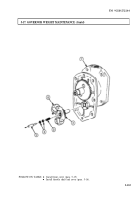
Governor weight must be installed before assembling throttle
shaft cover (para. 5-17).
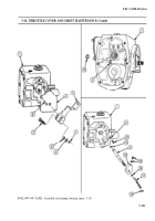
Install new O-ring (11) and valve plug (12) in fuel pump housing (1).
Install fuel-adjusting screw (17), new O-rings (13) and (16), throttle stop control (14) and two
setscrews (15) on throttle shaft (9).
Install new throttle shaft ball (18) in end of throttle shaft (9).
Install throttle shaft (9) in fuel pump housing (1) with retaining ring (10).
NOTE
l
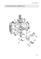
Do not install throttle shaft cover until fuel pump has been
calibrated (para. 5-18).
l
Do not perform steps 5 through 7 unless pin holes are damaged
beyond use.
Position throttle shaft cover (2) on fuel pump housing (1).
CAUTION
Use care when drilling new holes for drive pins. The pump
housing is made of cast aluminum and is easily damaged. Do not
allow metal particles to enter pump housing.
Center punch location of new holes on throttle shaft cover (2). Ensure holes are opposite one
another.
Carefully drill through throttle shaft cover (2) and into throttle shaft cover flange with 1/15 in. drill
bit NO MORE than 1/4 in. (6 mm).
Install throttle shaft cover (2) on fuel pump housing (1) by gently tapping two new drive pins (8)
through throttle shaft cover (2) into holes.
Install throttle lever (3) on throttle shaft (9) with screw (7), washer (6), new lockwasher (5), and
nut (4).
5-100
Back to Top


