TM-9-2320-272-24-4 - Page 104 of 836
TM 9-2320-272-24-4
5-16. THROTTLE COVER AND SHAFT MAINTENANCE
THIS TASK COVERS:
a. Disassembly
b. Inspection
c. Assembly
INITIAL SETUP:
APPLICABLE MODELS
REFERENCES (TM)
M939/A1
TM 9-2320-272-24P
TOOLS
EQUIPMENT CONDITION
General mechanic’s tool kit (Appendix E, Item 1)
Fuel pump housing disassembled (para. 5-15).
MATERIALS/PARTS
Two drive pins (Appendix D, Item 101)
O-ring (Appendix D, Item 461)
O-ring (Appendix D, Item 462)
O-ring (Appendix D, Item 463)
Lockwasher (Appendix D, Item 400)
Throttle shaft soft ball bearing (Appendix D,
Item 666)
a. Disassembly
1.
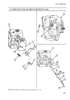
Center punch and drill out the two drive pins (8) connecting the fuel pump housing (1) to throttle
shaft cover (2). Discard drive pins (8).
2.
Remove nut (4), lockwasher (5), washer (6), screw (7), throttle lever (3), and throttle shaft cover (2)
from fuel pump housing (1). Discard lockwasher (5).
3.
Remove retaining ring (10) and throttle shaft (9) from fuel pump housing (1).
4.
Drill and remove soft ball bearing (18) from throttle shaft (9). Discard soft ball bearing (18).
5.
Remove two set screws (15) and throttle stop control (14) from throttle shaft (9).
6.
Remove O-rings (13) and (16), fuel-adjust screw (17), valve plug (12), and O-ring (11) from throttle
shaft (9). Discard O-rings (13), (16), and (11).
b. Inspection
1.
Inspect throttle shaft (9) for scoring, nicks, and scratches. If scored, nicked, or scratched, replace
throttle shaft (9).
5-98
Back to Top


