TM-9-2320-272-24-4 - Page 610 of 836
5-100. 3 PHASE
TM 9-2320-272-24-4
THIS TASK COVERS:
a. Removal
b. Installation
INITIAL SETUP:
APPLICABLE MODELS
EQUIPMENT CONDITION
M934/A1/A2
Parking brake set (TM 9-2320-272-10).
TOOLS
Battery ground cables disconnected (para. 3-126).
General mechanic’s tool kit (Appendix E, Item 1)
Ceiling filter and side panels removed (para. 5-79).
REFERENCES (TM)
TM 9-2320-272-10
TM 9-2320272-24P
NOTE
Tag wires for installation.
1.
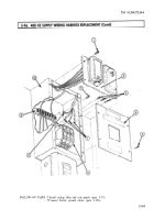
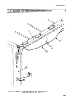
Remove six screws (1) and cover (12) from load center (5).
2.
Remove screw (3) and clamp (13) from wiring harness (2) and van body (4).
3.
Remove screw (8) and wire (6) from neutral bus (7).
4.
Remove three screws (10) and wires (11) from circuit breakers (9).
5.
Remove twelve screws (16) and clamps (15) from van ceiling (14) and wiring harness (2).
6.
Remove wiring harness (2) from van body (4).
1.
Position wiring harness (2) on van body (4).
2.
Install wiring harness (2) on van ceiling (14) with twelve clamps (15) and screws (16).
3.
Install three wires (11) on circuit breakers (9) with three screws (10).
4.
Install wire (6) on neutral bus (7) with screw (8).
5.
Install clamp (13) on wiring harness (2) and van body (4) with screw (3).
6.
Install cover (12) on load center (5) with six screws (1).
5-604
Back to Top


