TM-9-2320-272-24-4 - Page 604 of 836
5-98. RIGHT
TM 9-2320-272-24-4
THIS TASK COVERS:
a.
Removal
c. Installation
b.
Repair
INITIAL SETUP:
APPLICABLE MODELS
M934/A1/A2
TOOLS
EQUIPMENT CONDITION
Parking brake set (TM 9-2320-272-10).
Van body sides fully expanded and secured
(TM 9-2320-272-10).
General mechanic’s tool kit (Appendix E, Item 1)
Hinged roof-operated blackout circuit plungers
REFERENCES (TM)
removed (para. 3-377).
TM 9-2320-272-10
TM 9-2320-272-24P
NOTE
Tag wires for installation.
1.
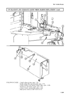
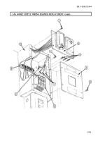
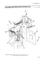
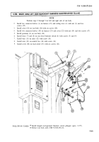
Remove six screws (20) and cover (19) from load center (16).
2.
Remove screw (14) and wire (13) from neutral bus (15).
3.
Remove screw (10) and wire (11) from relay (12).
4.
Remove screws (5) and (9) and wires (7) and (8) from rear door blackout switch (6).
NOTE
Perform steps 5 through 7 for left and right side of van body.
5.
Remove six screws (24), cover (22), and grommet (4) from van body (26).
6.
Remove nut (21), two screws (17), and two connector halves (18) from harness (23) and cover (22).
7.
Remove nut (3), two screws (25), and two connector halves (1) from harness (23) and ceiling
truss (2) and pull harness (23) through hole in ceiling truss (2).
5-598
Back to Top


