TM-9-2320-273-34 - Page 560 of 801
TM9-2320-273-34
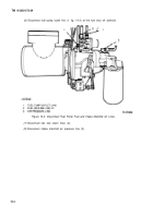
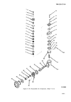
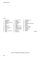
(5) Remove the O-ring (6) from the unloader body and discard.
(6) Lift the unloader cap spring (9) from the inlet valve seat (10).
(7) Remove the unloader cap (8) from the unloader valve body (4).
(8) Remove the unloader seal (7) from inside the unloader body.
(9) Remove the wear plate (5) from the unloader body.
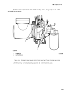
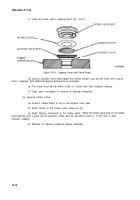
(10) Insert a large screwdriver into the slots of the inlet valve seat (10) and rotate the seat
from the cylinder head.
(11) Remove the inlet valve (11) and spring (12) from the cylinder head. Throw away spring (12).
(12) Remove the four cylinder head capscrews (18), Iockwashers (19), and washers (20); then
remove cover (21), gasket (22), compressor head (23), and gasket (24). Discard the gasket (24).
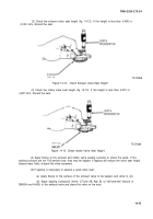
(13) press the exhaust valve (16) from the underside of the head with thumb pressure.
(14) Remove the 0-rings (13) and (15) from the exhaust valve seat (14).
(15) Remove exhaust valve (16) and spring (17) from the exhaust valve seat (14). Throw away
spring (17).
b. Crankcase Group.
NOTE
The crankcase group consists of the
crankcase, support, crankshaft,
connecting rod, and piston assembly.
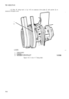
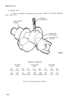
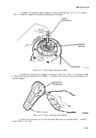
(7) Using a coupling puller, pull the coupling half (40) from the crankshaft and remove
thrust washer (39).
(2) Remove four capscrews (42) securing the support (37) to the crankcase (32). Remove
support (37) and gasket (36). Discard the gasket.
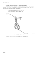
(3) Remove crankshaft (35) from crankcase (32) and connecting rod (31 ).
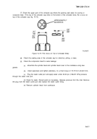
(4) Clean any carbon from the worn ridge at the top bore of the crankcase (32) and then
push the piston (28) and connecting rod (31 ) out the top of the crankcase.
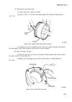
(5) Remove compression rings (25) and (26) and oil control ring (27). Discard the rings.
(6) Remove the two snap rings
(30).
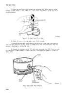
(7) Place
the piston (28) in hot water to expand the piston pin bore.
CAUTIO N
Do not drive the pin from the
as this will distort the piston.
(8) Push the piston pin (29) from the piston (28)
piston,
and remove connecting rod (31).
14-13
Back to Top

