TM-9-2320-279-20-1 - Page 934 of 985
TM 9-2320-279-20-1
d.
e.
Electrical System Maintenance Instructions (Cont)
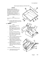
(1)
Install box (1) on fender (2) with four
screws (3) and locknuts (4).
(2)
Install clamp (5), two washers (6),
screw (7), lockwasher (8), and nut (9).
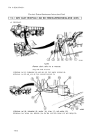
Installation.
NOTE
Replace plastic cable ties as necessary.
(3)
Install wire (10) on solenoid terminal (11) with nut (12).
(4)
Install wire (13) on starter ground terminal (14) with
lockwasher (15) and nut (16).
Follow-on Maintenance.
(1)
Close left side engine cover (TM 9-2320-279-10).
(2)
Connect batteries (para 7-91).
END OF TASK
Section Xl. CHASSIS WIRING COMPONENTS
7-93. RESISTOR MODULE REMOVAL/INSTALLATION.
This task covers:
a. Removal
c. Follow-on Maintenance
b. Installation
INITIAL SETUP
Models
References
All
None
Test Equipment
Equipment Condition
None
TM or Para
Condition Description
Special Tools
TM 9-2320-279-10 Shut off engine.
None
Special Environmental Conditions
Supplies
None
Tags, identification, Item 48, Appendix C
General Safety Instructions
Personnel Required
None
MOS 63S, Heavy wheel vehicle mechanic
7-349
Back to Top


