TM-9-2320-279-34-3 - Page 15 of 717
TM 9-2320-279-34-3
Figure
17-1
17-2
17-3
17-4
17-5
17-6
17-7
17-8
17-9
17-10
17-11
17-12
17-13
17-14
17-15
17-16
17-17
17-18
17-19
17-20
17-21
17-22
17-23
17-24
17-25
18-1
18-2
18-3
18-4
18-5
18-6
18-7
18-8
18-9
18-10
18-11
18-12
18-13
18-14
18-15
22-1
22-2
22-3
22-4
22-5
B-1
B-2
B-3
B-4
B-5
B-6
B-8
B-7
B-9
B-10
B-11
B-12
B-13
B-14
B-15
FO-1
FO-2
FO-3
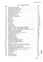
LIST OF ILLUSTRATIONS
Title
Page
Hoist Hoses and Tubes (Left Side) .
............................................
17-5
Hoist Hoses and Tubes (Right Side) .
...........................................
17-6
Telescoping Cylinders, Hoses, and Tubes.
.......................................
17-7
Telescoping Cylinders, Hoses, and Tubes.
.......................................
17-8
Boom Cylinders, Hoses, and Tubes .
...........................................
17-9
Boom Cylinders, Hoses, and Tubes
Mast Erection Cylinders, Hoses, and Tubes.
..................................
17-10
..................................
17-11
Swing Drive Hoses and Tubes.
................................................
17-12
Main Hydraulic Hoses and Tubes
17-13
....................................
Main Control Valve
..................................
17-15
Overload Solenoid (M977 Only).
..........................
17-16
Hoist Hoses and Tubes (Left Side)
17-16.4
Hoist Hoses and Tubes (Right Side)
17-16.5
Lift Cylinder
Swing Drive
Main Lines
.............................
..............................
................................
...........................................
.............................................
17-16.6
17-16.7
17-16.8
Shutdown Valves.
..........................................................
17-16.9
Shutdown Valves.
..........................................................
17-16.10
Accumulator.
. ............................................................
17-16.11
Control Valve.
.............................................................
17-16.12
Control Valve.
.............................................................
17-16.13
Control Valve.
.............................................................
17-16.14
Left Hand Valve.
...........................................................
17-16.15
Outrigger Manifold
Outrigger Cylinders
........................................................
17-16.16
.......................................
17-16.17
Extensions No. 3 and No. 4 Hoses and Tubes (Hose Reel Side)
......................
18-76
Extensions No. 3 and No. 4 Hoses and Tubes (Hose Reel Side)
......................
18-77
Extensions No. 1 and No. 2 Hoses and Tubes (Hose Reel Side)
......................
18-78
Extensions No. 1 and No. 2 Hoses and Tubes (Hoist Cable Tiedown Block Side).
.......
18-79
Extensions No. 1 and No. 2 Hoses and Tubes.
...................................
18-80
Hoist Hoses and Tubes (Hose Reel Side)
18-81
Hoist Hoses and Tubes (Hose Reel Side) .
...........................
.............................
18-82
Hoist Hoses and Tubes (Hoist Cable Tiedown Block Side) .
.........................
18-83
Inner Boom Hoses and Tubes.
.................................
..............................
18-84
Unfolding Cylinders Hoses and Tubes
Main Hydraulic Tubes
.............................
18-86
...................................
.................................
18-85
18-87
Slewing System Tubes
Outrigger Control Tubes
18-88
18-89
Outrigger Hoses and Tubes
18-90
Main Control Valve Ports
...............................
..................................
22-5
Tanker External Components
..........................
Tanker Filter and Manual Dispensing Components
22-6
Tanker Dispensing Components-Valves
.........................
....................
Tanker Loading and Unloading Components.
22-7
22-8
Tanker Gages, Air, and Electrical Components
Lifting Eyes (PN 2BH944).
..........................
22-9
B-2
..........................
...................
Shims.
. ..................................................................
B-2
Detent Ball Compression Tool (Heavy-Duty Winch) (PN IPP161).
...............
...................
B-3
Crane Hoist Drive Unit Pressure Plate RemovaI/InstaIiation Tool (M983)
B-3
Arctic Heater Test Set .
.....................................................
B-4
Hydraulic Hand Pump Tool (M983) (PN 2CS30)
Hydraulic Hand Pump Tool (M983) (PN 2CS31)
................
........................
B-6
B-7
B-9
V5 Air Actuated Valve Spring Compression Tool (M978) (PN 2SK886)
UnloaderBoreBushing Tool
B-10
Air compressor Cylinder Head Removal Tool (PN 2AH762).
Spanner Socket.
........................................
................
.........
................................
B-10
B-10
B-14
Hoses and Hose Assemblies
Locking Strips
...................................
Locking Channel.
..........................................
Harness Wire.
.................................
.....................................
B-18
Hydraulic Schematic
B-17
B-18
Crane Wiring Diagrams.
..............................
FP-1
FP-23
Crane Electrical Schematic
.................................
...........................
FP-29
Change 1
iii
Back to Top

