TM-9-2320-280-20-2 - Page 172 of 951
3-84. TENSIONER, IDLER PULLEYS, AND MOUNTING HARDWARE REPLACEMENT
This task covers:
a. Removal
b.
Installation
a. Removal
1.
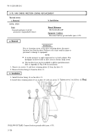
Remove capscrew (12) and tensioner (11) from mounting bracket (8).
NOTE
On M997A2 vehicles equipped with A/C, the compressor pulley is
in place of the lower idler pulley.
2.
Remove three nuts (6), lockwashers (5), washers (4), capscrews (1), washers (2), and idler pulleys
(3) from mounting bracket (8). Discard lockwashers (5).
3.
Remove two capscrews (10), lockwashers (9), and mounting bracket (8) from water pump (7).
Discard lockwashers (9).
INITIAL SETUP:
Applicable Models
M997A2, M1025A2, M1035A2, M1043A2,
M1045A2, M1097A2, M1123
Tools
General mechanic’s tool kit:
automotive (Appendix B, Item 1)
Materials/Parts
Two lockwashers (Appendix G, Item 191)
Three lockwashers (Appendix G, Item 190)
Equipment Condition
• Fan drive and fan blade removed (para. 3-78).
• Serpentine drivebelt removed (para. 3-83).
b. Installation
1.
Install mounting bracket (8) on water pump (7) with two lockwashers (9) and capscrews (10).
NOTE
• On M997A2 vehicles equipped with A/C, the compressor pulley is
in place of the lower idler pulley.
• Pulley will turn if it is installed correctly. If pulley does not turn,
it may be installed backwards.
2.
Install three idler pulleys (3) on mounting bracket (8) with three washers (2), capscrews (1),
washers (4), lockwashers (5), and nuts (6).
3.
Install tensioner (11) on mounting bracket (8) with capscrew (12).
TM 9-2320-280-20-2
3-144
Change 3
Back to Top

