TM-9-2320-280-20-2 - Page 224 of 951
4-5.9. (6.5L) 200 AMPERE DUAL VOLTAGE ALTERNATOR (12447109) UMBILICAL POWER
CABLE REPLACEMENT
This task covers:
a. Removal
b. Installation
INITIAL SETUP:
Tools
General mechanic’s tool kit:
automotive (Appendix B, Item 1)
Materials/Parts
Two lockwashers (Appendix G, Item 138)
Lockwasher (Appendix G, Item 148)
Lockwasher (Appendix G, Item 150)
Sealing compound (Appendix C, Item 47.1)
Personnel Required
One mechanic
One assistant
Manual References
TM 9-2320-280-24P
Equipment Condition
• Batteries removed (para. 4-79).
• Fixed rear door removed (para. 10-14).
TM 9-2320-280-20-2
4-12.24
Change 3
NOTE
Prior to removal, tag leads for installation.
1.
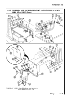
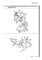
Remove nut (5), lockwasher (4), washer (3), and positive power cable (2) from buss bar (1). Discard
lockwasher (4).
2.
Remove capscrew (6), lockwasher (7), negative power cable (8), and two cables (9) from shunt (10).
Discard lockwasher (7).
3.
Remove five capscrews (20), two lockwashers (19), washers (18), and coverplate (17) from “B” beam (12).
Discard lockwashers (19).
4.
Remove two nuts (15), washers (14), capscrews (25), washers (26), and mounting bracket (27) from
coverplate (17).
5.
Remove nut (28), screw (23), and cover chain (21) from mounting bracket (27).
6.
Remove cover (22) with cover chain (21) from umbilical power cable assembly (29).
7.
Remove four nuts (30), screws (24), and mounting bracket (27) from umbilical power cable assembly (29).
8.
Pull umbilical power cable assembly (29) through grommet (11) and coverplate (17), and remove
from vehicle (16).
9.
Remove grommet (11) from battery box (13).
1.
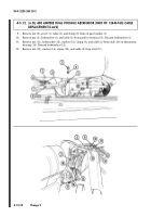
Install grommet (11) on battery box (13).
2.
Route umbilical power cable assembly (29) through coverplate (17) and grommet (11), and position
in approximate mounting location on vehicle (16).
3.
Install cover chain (21) on mounting bracket (27) with screw (23) and nut (28).
4.
Install umbilical power cable assembly (29) on mounting bracket (27) with four screws (24) and
nuts (30).
5.
Install cover (22) on umbilical power cable assembly (29).
6.
Install coverplate (17) on “B” beam (12) with two washers (18), lockwashers (19), and five
capscrews (20).
7.
Install mounting bracket (27) on coverplate (17) with two washers (26), capscrews (25), washers (14),
and nuts (15).
8.
Install two cables (9) and negative power cable (8) on shunt (10) with lockwasher (7) and
capscrew (6).
9.
Install positive power cable (2) on buss bar (1) with washer (3), lockwasher (4), and nut (5).
10.
Apply silicone compound to cable (2), coating all exposed metallic surfaces.
b. Installation
a. Removal
Back to Top


