TM-9-2320-280-20-2 - Page 540 of 951
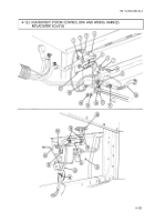
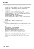
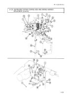
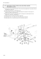
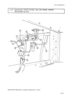
4-123. HEATER/VENT SYSTEM CONTROL BOX AND WIRING HARNESS
REPLACEMENT (Cont’d)
b. Installation
8.
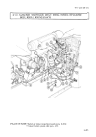
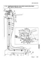
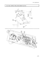
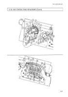
Remove three screws (20), clamps (21), harness (2), and battery cable harness (22) from body (5).
9.
Remove four screws (19), lockwashers (18), and cover (17) from circuit box (4). Discard
lockwashers (18).
10.
Remove plain-assembled nut (16) and clamp (15) from harness (2) and screw (24). Discard plain-
assembled nut (16).
11.
Remove three screws (14) from harness leads (13) and terminal block (25).
12.
Remove three screws (12), clamps (11), and harness (2) from NBC harness (10) and body (5).
13.
Remove two screws (9), washers (8), retainer (7) and grommet (6 ) from body (5) and harness (2).
14.
Route harness (2) through grommet (6) hole in body (5).
15.
Remove five screws (28) and clamps (29) from harness (2) and body (5).
16.
Remove three nuts (33), lockwashers (34), capscrews (36), and clamps (35) from harness (2) and body
(5). Discard lockwashers (34).
17.
Disconnect plug (27) from heater receptacle (26).
18.
Remove plug button (30) and control lever linkage (31) from duct door arm (32). Discard plug
button (30).
19.
Remove four screws (23), control box (1), and harness (2) from body (5).
TM 9-2320-280-20-2
4-294
Change 3
1.
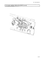
Route harness (2) through control box opening (3) in body (5) and install control box (1) on body (5)
with four screws (23).
2.
Attach control lever linkage (31) to duct door arm (32) with plug button (30).
3.
Install three clamps (35) on harness (2) and body (5) with capscrews (36), lockwashers (34), and nuts
(33).
4.
Connect control box plug (27) to heater receptacle (26).
5.
Route harness (2) through grommet (6) hole in body (5).
6.
Install five clamps (29) on harness (2) and body (5) with five screws (28).
7.
Install three harness leads (13) to terminal block (25) with three screws (14).
8.
Install clamp (15) on harness (2) and screw (24) with plain-assembled nut (16).
9.
Install grommet (6) and retainer (7) on harness (2) and body (5) with two washers (8) and screws
(9).
10.
Install harness (2) in three clamps (11) with NBC harness (10), on body (5) with three screws (12).
11.
Install cover (17) on circuit box (4) with four lockwashers (18) and screws (19).
12.
Install harness (2) in three clamps (21) with battery cable harness (22), on body (5) with three
screws (20).
Back to Top

