TM-9-2320-280-20-2 - Page 603 of 951
5-13. TRANSMISSION SHIFT ROD MAINTENANCE (4L80-E)
This task covers:
a. Removal
c. Adjustment
b. Installation
a. Removal
1.
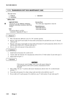
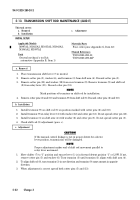
Place transmission shift lever (7) in neutral.
2.
Remove cotter pin (5), washer (6), and trunnion (3) from shift arm (4). Discard cotter pin (5).
3.
Remove cotter pin (13) and washer (12) from rear trunnion (9). Remove trunnion (9) and shift rod
(8) from relay lever (11). Discard cotter pin (13).
NOTE
Mark positions of trunnions on shift rod for installation.
4.
Remove cotter pins (2) and (10) and trunnion (9) from shift rod (8). Discard cotter pins (2) and (10).
INITIAL SETUP:
Applicable Models
M997A2, M1025A2, M1035A2, M1043A2,
M1045A2, M1097A2
Tools
General mechanic’s tool kit:
automotive (Appendix B, Item 1)
Materials/Parts
Four cotter pins (Appendix G, Item 12)
Manual References
TM 9-2320-280-10
TM 9-2320-280-24P
b. Installation
1.
Install trunnion (9) on shift rod (8) on position marked with cotter pins (2) and (10).
2.
Install trunnion (9) on relay lever (11) with washer (12) and cotter pin (13). Do not spread cotter pin (13).
3.
Install trunnion (3) on shift arm (4) with washer (6) and cotter pin (5). Do not spread cotter pin (5).
4.
Check shift rod (8) adjustment (para. c).
c. Adjustment
CAUTION
If the manual control linkage is not in proper detent for selector
lever position, transmission will be damaged.
NOTE
Proper adjustment makes end of shift rod movement parallel to
relay lever movement.
1.
Move shifter (7) to “1” position and ensure lever (1) is in forward detent position “1” or LOW. If not,
remove cotter pin (5) and washer (6). Turn trunnion (3) until trunnion (3) aligns with shift arm (4).
2.
To align shift rod (8), turn trunnion (3) in one direction and trunnion (9) same amount in opposite
direction.
3.
When adjustment is correct spread both cotter pins (5) and (13).
TM 9-2320-280-20-2
5-32
Change 3
Back to Top

