TM-9-2320-280-20-2 - Page 634 of 951
TM 9-2320-280-20-2
6-2. FRONT PROPELLER SHAFT ASSEMBLY MAINTENANCE (Cont’d)
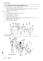
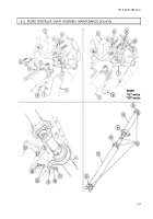
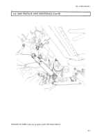
1. Install front propeller shaft assembly (4) over exhaust pipe (8) and over top of transfer case (5).
2. Install front propeller shaft assembly (4) on differential pinion yoke (1) with two bearing straps (2)
and four capscrews (3). Tighten capscrews (3) to 13-18 lb-ft (18-24 N m).
3. Install center bearing (19) on engine mount (21) with two washers (18), capscrews (20), washers (18),
and nuts (17). Tighten capscrews (20) to 60 lb-ft (81 N m).
4. Install transfer case shift rod (11) on transfer case shift lever (6) with washer (12) and cotter pin (13).
NOTE
Step 5 applies to all vehicles except M1097, “A1” and “A2” series.
Step 6 applies to M1097, “A1” and “A2” series.
5. Install front propeller shaft assembly (4) on transfer case output yoke (7) with two bearing straps (9)
and four capscrews (10). Tighten capscrews (10) to 13-18 lb-ft (18-24 N m).
6. Install front propeller shaft assembly (4) on transfer case output yoke (7) with two U-bolts ( 16), four
washers (15), and nuts (14). Tighten nuts (14) to 13-18, lb-ft (18-24 N m).
6-4
Back to Top


