TM-9-2320-280-20-2 - Page 638 of 951
CAUTION
Prior to towing vehicle, parking brake rotor must be removed.
NOTE
On vehicles with serial numbers USBL Eff. 44825 and above, the
propeller shaft is attached to the differential yoke instead of the
parking brake rotor. Lockwashers and U-bolts are not used.
1.
Chock wheels and release parking brake (TM 9-2320-280-10).
2.
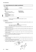
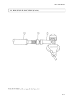
Remove four nuts (1), lockwashers (2), and two U-bolts (4) from rear propeller shaft (5) and transfer
case output yoke (3). Discard lockwashers (2).
3.
Remove four capscrews (8), lockwashers (7), and rear propeller shaft (5) from parking brake
rotor (6). Discard lockwashers (7).
1.
Inspect propeller shaft (5) for cracks and dents. Replace if cracked or dented.
2.
Inspect grease fittings and universal joints for serviceability. Replace universal joints (para. 6-7)
or grease fittings if unserviceable.
1.
Install rear propeller shaft (5) on parking brake rotor (6) with four lockwashers (7) and cap-
screws (8). Tighten capscrews (8) to 60 lb-ft (81 N
•
m).
2.
Install rear propeller shaft (5) on transfer case output yoke (3) with two U-bolts (4), four lock-
washers (2), and nuts (1). Tighten nuts (1) to 21 lb-ft (28 N
•
m).
3.
Apply parking brake (TM 9-2320-280-10) and remove wheel chocks.
c. Installation
b. Inspection
a. Removal
6-4. REAR PROPELLER SHAFT MAINTENANCE
Materials/Parts
Four lockwashers (Appendix G, Item 134)
Four lockwashers (Appendix G, Item 170)
Manual References
TM 9-2320-280-10
TM 9-2320-280-24P
TM 9-2320-280-20-2
6-8
Change 3
This task covers:
a. Removal
c. Installation
b. Inspection
INITIAL SETUP:
Applicable Models
All except M1097, “A1” and “A2” series
Tools
General mechanic’s tool kit:
automotive (Appendix B, Item 1)
Back to Top

