TM-9-2320-280-20-3 - Page 427 of 1168
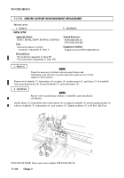
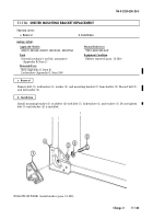
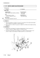
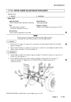
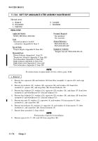
11-120. SHELTER REPLACEMENT
This task covers:
a. Removal
b. Installation
INITIAL SETUP:
Applicable Models
M1037, M1042, M1097, M1097A1, M1097A2
Tools
General mechanic’s tool kit:
automotive (Appendix B, Item 1)
Materials/Parts
Eight lockbolts (Appendix G, Item 69)
Eight lockwashers (Appendix G, Item 179)
Personnel Required
One mechanic
One assistant
Manual References
TM 9-2320-280-10
TM 9-2320-280-24P
Equipment Condition
Tailgate lowered (TM 9-2320-280-10).
General Safety Instructions
Direct all personnel to stand clear during hoisting
operations.
TM 9-2320-280-20-3
11-168
Change 2
WARNING
Direct all personnel to stand clear during hoisting operations. A
heavy, swinging load can be extremely dangerous.
1.
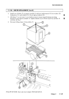
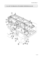
Position chain hoist (2) over top of shelter (3).
2.
Connect lifting chains (1) to chain hoist (2) and four corners of shelter (3).
NOTE
It may be necessary to detach cab rear panel straps and
turnbuttons and roll cab rear panel upward to gain access to front
mounting brackets.
3.
Remove eight lockbolts (12), lockwashers (11), washers (10), and four reinforcements (9) from four
mounting brackets (6) and support assembly (4), and remove shims (7), if present. Discard
lockbolts (12) and lockwashers (11).
4.
Remove shelter (3) from support assembly (4) and vehicle body with chain hoist (2).
5.
Remove mounting brackets (para. 11-116).
WARNING
Direct all personnel to stand clear during hoisting operations. A
heavy, swinging load can be extremely dangerous.
1.
Install mounting brackets (para. 11-116).
2.
Install shelter (3) over support assembly (4) and gradually lower shelter (3) into position on support
assembly (4).
NOTE
Shelter should be tightly fitted to front of support assembly and
centered from side to side. Shims should only be added to rear
shelter mounts.
3.
Position shelter (3) on support assembly (4) and front mounting points (5) and install front of
shelter (3) on front of support assembly (4) with two reinforcements (9), four washers (10),
lockwashers (11), and lockbolts (12). Tighten lockbolts (12) to 90 lb-ft (122 N
•
m) and bolts (8)
to 60 lb-ft (81 N
•
m).
b. Installation
a. Removal
Back to Top

