TM-9-2320-280-20-3 - Page 455 of 1168
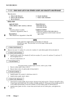
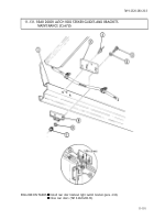
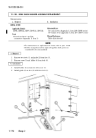
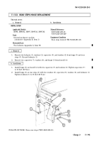
11-135. REAR STEPS LATCH ASSEMBLY MAINTENANCE
This task covers:
a. Removal
c. Adjustment
b. Installation
a. Removal
1.
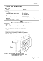
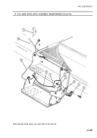
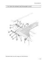
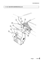
Open split ring (7) from release cable (8) and latch (5).
2.
Remove three locknuts (2), washers (3), capscrews (6), shim (4), and latch (5) from step frame (9).
Discard locknuts (2).
NOTE
The procedure for replacing left and right latch assemblies is
basically the same. This procedure covers the right latch assembly.
INITIAL SETUP:
Applicable Models
M996, M996A1, M997, M997A1, M997A2
Tools
General mechanic’s tool kit:
automotive (Appendix B, Item 1)
Materials/Parts
Three locknuts (Appendix G, Item 70)
Manual References
TM 9-2320-280-10
TM 9-2320-280-24P
Equipment Condition
Rear steps lowered (TM 9-2320-280-10).
b. Installation
1.
Install shim (4) and latch (5) on step frame (9) with three capscrews (6), washers (3), and locknuts (2).
Tighten locknuts (2) to 6 lb-ft (8 N
•
m).
2.
Install release cable (8) on latch (5) with split ring (7) and close split ring (7).
c. Adjustment
1.
Loosen six locknuts (2) on latch (5) from step frame (9).
2.
Raise rear steps (TM 9-2320-280-10) and ensure step latches (5) are engaged on strikers (1).
3.
Press rear step assembly firmly against body (10), hold in place, and tighten six locknuts (2) on
latches (5) and step frame (9).
4.
Lower rear steps (TM 9-2320-280-10) and tighten six locknuts (2) to 6 lb-ft (8 N
•
m).
5.
If latches (5) do not center on strikers (1), add or remove shims (4).
TM 9-2320-280-20-3
11-196
Change 2
Back to Top

