TM-9-2320-280-20-3 - Page 902 of 1168
TM 9-2320-280-20-3
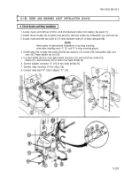
12-185. SIREN AND WARNING LIGHT INSTALLATION (Cont’d)
5.
6.
7.
8.
9.
10.
11.
12.
13.
14.
15.
16.
17.
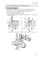
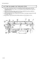
Install driver’s side siren switch (15) on dash panel (14) with two lockwashers (12) and screws (13).
Route fabricated wire “G” (17) along tunnel (27) and connect connector (24) to lead (22) of
passenger’s side siren switch.
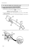
On driver’s side, connect wire “G” (17) connector (30) to adapter connector “E” (28).
Connect lead (29) of driver’s side siren switch (15) to adapter connector “E” (28).
Connect lead (31) of driver’s side siren switch (15) to adapter connector “B” (32).
On driver’s side, connect one end of fabricated wire “D” (33) to adapter “B” (32), and the other end to
adapter connector “A” (34).
On driver’s side, connect lead “B” (35) of relay (36) to adapter “A” (34).
Route fabricated wire “F" (16) along tunnel (27), and connect connector (25) to lead (23) of
passenger’s side siren switch (21).
On driver’s side, connect wire "F" (16) to adapter connector “B” (32).
Locate, mark, and drill three 0.146-in. (3.7-mm) diameter holes (20) in right side engine panel (19)
and vehicle tunnel (27).
Install wires "F" (16) and “G” (17) on panel (19) with clamp (26) and screw (18).
Install wires “F” (16) and “G” (17) on tunnel (27) with five clamps (26) and screws (18).
Tuck exposed wires under vehicle insulation on tunnel (27).
12-289
Back to Top


