TM-9-2320-280-34 - Page 509 of 1258
TM 9-2320-280-34
9-6.
GEARED HUB REPAIR
This task covers:
a.
Disassembly
c.
Installation
b.
Cleaning
d.
Assembly
INITIAL SETUP:
Tools
Manual References
General mechanic's tool kit:
TM 9-2320 280-20
automotive (Appendix G, Item 1)
TM 9-2320-280-24
Dial indicator (Appendix G, Item 95)
Blind hole puller set
Equipment Condition
(Appendix G.
Item 138) optional
Geared hub removed (TM 9-2320-280-20).
Special Tools
General Safety Instructions
Input seal installer (Appendix G, Item 88)
Ensure locktab on lockwasher is bent completely
Spindle seal installer (Appendix G.
Item 90) into slot on retaining nut.
Eight-slotted retaining
Driver handle (Appendix G, Item 66)
nut provides additional security by enabling two
Geared hub locknut wrench
locktabs to be bent into slots on retaining nut.
(Appendix G, Item 89)
Materials/Parts
Maintenance Level
Input seal (Appendix E, Item 179)
Direct support
Spindle seal (Appendix E, Item 183)
Spindle lockwasher (Appendix E, Item 93)
Anaerobic sealer (Appendix B, Item 45)
Sealing compound (Appendix B, Item 49)
Grease (Appendix B, Item 20)
a.
Disassembly
1.
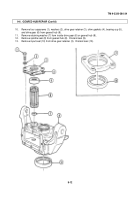
Position geared hub (4) with spindle (5) supporting geared hub (4).
2.
Remove eight capscrews (1), washers (2), and side cover (3) from geared hub (4).
NOTE
If backlash between drive and driven gears is more than 0.018 in.
(0.46 mm) both gears must be replaced.
3.
Mount dial indicator on geared hub (4) and index indicator to register from one drive gear (7) tooth.
Move drive gear (7) back and forth while holding driven gear (6) stationary to read backlash.
9-10
Back to Top

