TM-9-2320-280-34 - Page 515 of 1258
9-6.
GEARED HUB REPAIR (Cont'd)
8.
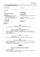
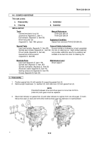
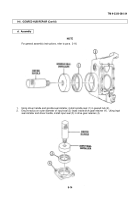
Install driven gear (13), inner bearing spindle spacer (8), and bearing spacer (7.1) (A2 and M1123
vehicles only) in geared hub (9).
9.
Install outer bearing spacer (10) on spindle (11).
10.
Lower geared hub (9) onto spindle (11) and align splines on driven gear (13) with splines on
spindle (11). Make sure outer spindle bearing (12) seats in bearing cup.
NOTE
Steps 10.1 and 10.2 apply to A2 and M1123 vehicles only.
10.1.
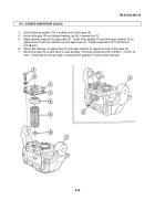
Install spindle extension (3.1) on spindle (11).
10.2.
Install seal (3.3) and retaining ring (3.4) on steering arm cover (3.2).
11.
Apply grease to face of retaining nut (4).
12.
Install inner bearing (7), washer (6), lockwasher (5), and retaining nut (4) on spindle (11).
13.
Using retaining nut wrench, tighten retaining nut (4) to 40 lb-ft (54 N
•
m) while rotating geared
hub (9) back and forth to seat bearings (7) and (12).
14.
Loosen and retighten retaining nut (4) to 23-27 lb-ft (31-37 N
•
m).
WARNING
Ensure locktab on lockwasher is bent completely into slot on
retaining nut. Failure to do this may cause injury to personnel or
damage to equipment.
NOTE
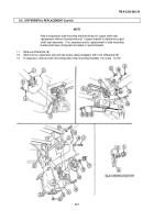
For new configuration, two locktabs on lockwasher must be bent
into slots on retaining nut.
15.
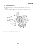
Determine which locktab (15) on lockwasher (5) aligns with slot (14) in retaining nut (4). Bend
locktab (15) into slot (14) on retaining nut (4).
NOTE
Immediately install steering arm cover after application of sealer.
16.
Apply anaerobic sealer to steering arm cover (3) and install steering arm cover (3) on geared hub (9).
17.
Apply sealing compound to capscrews (1). Install steering arm cover (3) on geared hub (9) with four
washers (2) and capscrews (1). Tighten capscrews (1) to 65 lb-ft (88 N
•
m).
TM 9-2320-280-34
9 - 1 6
Change 1
Back to Top

