TM-9-2320-280-34 - Page 710 of 1258
1 4 - 2 0 . AIR-CONDITIONING EVA P O R ATOR MAINTENANCE (Cont'd)
1.
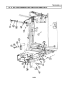
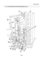
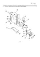
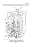
Remove low pressure switch (23) form outlet line (25).
2.
Remove two capscrews (13), nuts (16), clamps (14), and pressure lines (11) and (19) from
brackets (17).
3.
Disconnect pressure lines (19) and (11) from sight glass (20) and remove sight glass (20), pressure
line (19), and two O-rings (12). Discard O-rings (12).
4.
Disconnect pressure line (11) from expansion valve (4). Remove and discard O-ring (10).
5.
Remove two capscrews (6), nuts (18), brackets (17), and spacers (15) from evaporator (2).
6.
Disconnect expansion valve line (5) from outlet line (25). Remove and discard O-ring (7).
7.
Remove moisture seal (24) from evaporator outlet line (25) and expansion valve control tube (8).
Discard moisture seal (24).
8.
Loosen clamp (9) securing control tube (8) to evaporator outlet line (25).
9.
Disconnect expansion valve (4) from evaporator inlet line (1) and remove expansion valve (4) and
O-ring (3). Discard O-ring (3).
10.
Remove two screws (22) and drain pan (21) from evaporator (2) .
11.
Inspect evaporator (2), expansion valve (4), pressure lines (11), (19), and (5), sight glass (20), and low
pressure switch (23) for stripped threads, cracks, evidence
of leakage, and damage. Replace sight
glass and any other component if cracked, damaged, threads are stripped, or leakage is evident.
1.
Install drain pan (21) on evaporator (2) with two screws (22).
CAUTION
• To prevent damage to control line tube during installation of
expansion valve, avoid excessive bending or kinking of expansion
valve control tube.
• Avoid over tightening of expansion valve control tube retaining
clamp.
NOT E
FR-12 systems require different O-rings and lubricating oil.
2.
Lubricate O-ring (3) with refrigerant oil, install O-ring (3) and connect expansion valve (4) on
evaporator inlet line (1).
3.
Lubricate O-ring (7) with refrigerant oil, install O-ring (7) and connect expansion valve line (5) on
outlet line (25).
4.
Install control tube (8) on outlet line (25) with clamp (9). Do not overtighten.
5.
Install low pressure switch (23) on outlet line (25).
6.
Insulate control tube (8), evaporator inlet line (1), and outlet line (25) with moisture seal (24).
7.
Install two brackets (17) and spacers (15) on evaporator (2) with two capscrew (6) and nuts (18).
8.
Lubricate O-ring (10) with refrigerant oil, install O-ring (10) and connect pressure line (11) on
expansion valve (4).
NOT E
Sight glass window must face away from outlet line.
9.
Lubricate two O-rings (12) with refrigerant oil, install two O-rings (12) and connect pressure
lines (11) and (19) on sight glass (20).
10.
Install two clamps (14) and pressure lines (11) and (19) on bracket (17) with two capscrews (13) and
nuts (16).
b. Disassembly
c. Assembly
TM 9-2320-280-34
1 4 - 1 1 0
Change 1
Back to Top

