TM-9-2320-280-34 - Page 718 of 1258
1 4 - 2 3 . CONDENSER ASSEMBLY REPLACEMENT
This task covers:
a.
Removal
b.
Installation
INITIAL SETUP:
Applicable Models
_______________
M997, M997A1, M997A2
To o l s
____
General mechanic's tool kit:
automotive (Appendix G, Item 1)
M a t e r i a l s / P a rt s
_____________
O-ring (Appendix E, Item 105)
Ten lockwashers (Appendix E, Item 72)
Lubricating oil (Appendix B, Item 35) (R-12 only)
Lubricating oil (Appendix B, Item 35.1)
(FR-12 only)
Personnel Require d
________________
One mechanic
One assistant
Manual Refere n c e s
________________
TM 9-2320-280-20
TM 9-2320-280-24P
Equipment Condition
_________________
• Intake and exhaust grilles removed
(TM 9-2320-280-20).
• Condenser fans removed (TM 9-2320-280-20).
• Dryer bottle removed (para. 14-19).
Maintenance Level
_______________
Direct support
1.
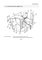
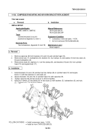
Remove eight screws (1) securing dryer bottle mounting panel (2) to fan support bracket (13) and
condenser housing (3).
2.
Remove eight capscrews (10) and lockwashers (11) securing dryer bottle mounting panel (2) and
fan bracket (13) to body (12). Discard lockwashers (11).
3.
Remove two nuts (7), lockwashers (8), and capscrews (9). Discard lockwashers (8).
4.
Remove nut (14), washer (15), and clamp (16) from screw (17) and slide wiring harness (18) to side.
5.
Turn fan support bracket (13) to allow removal through front intake grille opening. Remove fan
bracket (13).
6.
Disconnect compressor line (6) from condenser (4). Remove
and discard O-ring (5).
7.
Remove six screws (19) and condenser (4) from condenser housing (3).
CAUTION
______
Slowly remove condenser to avoid damage to the cooling fins.
Failure to do this will result in damage to equipment.
b. Installation
8.
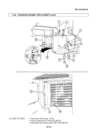
Remove condenser (4) through condenser blower housing opening into driver's compartment.
NOTE
FR-12 systems require different lubricating oil.
1.
Install condenser (4) on condenser housing (3) with six screws (19).
2.
Lubricate O-ring (5) and install O-ring (5) in compressor line (6). Connect compressor line (6)
to condenser (4).
3.
Install fan support bracket (13) on body (12) with two capscrews (9), lockwashers (8), and nuts (7).
4.
Install eight lockwashers (11) and capscrews (10) securing fan support bracket (13) and dryer panel
mounting panel (2) to body (12).
a. Removal
TM 9-2320-280-34
1 4 - 1 1 8
Change 1
Back to Top

