TM-9-2320-280-34 - Page 722 of 1258
1 4 - 2 5 . AIR-CONDITIONING SERVICE VA LVE REPLACEMENT
INITIAL SETUP:
Applicable Models
_______________
M997, M997A1, M997A2
To o l s
____
General mechanic's tool kit:
automotive (Appendix G, Item 1)
M a t e r i a l s / P a rt s
_____________
Two O-rings (Appendix E, Item 105)
Lubricating oil (Appendix B, Item 35) (R-12 only)
Lubricating oil (Appendix B, Item 35.1)
(FR-12 only)
Manual Refere n c e s
________________
TM 9-2320-280-20
TM 9-2320-280-24P
Equipment Condition
_________________
• Air-conditioning system discharged (para. 14-17).
• Air horn to air cleaner hose removed
(TM 9-2320-280-20).
General Safety Instructions
______________________
Air conditioner system must be discharged, prior
to replacing components.
Maintenance Level
_______________
Direct support
FOLLOW-ON TASKS: • Evacuate and charge air-conditioning system (para. 14-17).
• Install air horn to air cleaner hose (TM 9-2320-280-20).
1±
.
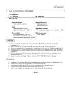
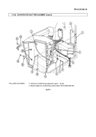
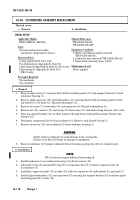
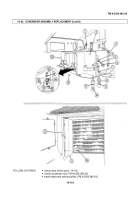
Disconnect suction line (1) from service valve (2).
2±
.
Remove suction service valve (2) and two O-rings (3) from compressor (4). Discard O-rings (3).
b. Installation
1±
.
Lubricate two O-rings (3) with refrigerant oil and install on suction service valve (2).
2±
.
Install suction service valve (2) on compressor (4).
3±
.
Connect suction line (1) to suction service valve (2).
________
WARNING
________
Air conditioner system must be discharged, prior to replacing components in
vapor system. Failure to do this may result in injury to personnel or damage
to equipment.
NO T E
• Suction (low pressure) and discharge (high pressure) service valves are
replaced basically the same. This procedure covers the suction service valve
• FR-12 service valves are replaced the same.
a. Removal
TM 9-2320-280-34
1 4 - 1 2 2
Change 1
This task covers:
a.
Removal
b.
Installation
Back to Top

