TM-9-2320-280-34 - Page 728 of 1258
TM 9-2320-280-34
14-27.
AIR-CONDITIONING COMPRESSOR REPAIR (Cont'd)
18.
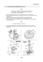
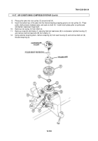
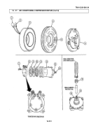
Insert seal remover and installer in seal housing (2) on seal assembly (1).
Press seal remover and
installer down against seal assembly (1) and twist clockwise to engage slots on seal assembly (1).
Remove seal assembly (1) from seal housing (2).
Discard seal assembly (1).
19.
Remove compressor cylinder block (8) from vise.
20.
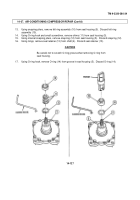
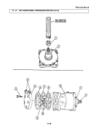
Remove five capscrews (3) and cylinder head (5) from compressor cylinder block (8).
21.
Using small plastic mallet, tap around outer edge of the cylinder head (5) to free it from valve plate
assembly (7).
Remove cylinder head (5) from valve plate assembly (7).
NOTE
Do not remove screw, nut, and lockwasher from center of valve plate
assembly.
22.
Position gasket scraper between valve plate assembly (7) and compressor cylinder block (8), and
lightly tap around edge to remove valve plate assembly (7).
Remove two gaskets (6) from valve plate
assembly (7).
Discard gaskets (6).
23.
Using gasket scraper, carefully remove any gasket (6) remains on cylinder head (5) and compressor
cylinder block (8).
c.
Inspection
1.
Inspect compressor shaft (9) and seal housing (2) for nicks, gouges, scrapes, or damage.
Replace
compressor assembly if shaft (9) or seal housing (2) is nicked, gouged, scraped, or damaged.
2.
Inspect compressor cylinder block (8) for cracks, stripped threads, and cracks or gouges in cylinder
walls.
Replace compressor assembly if cracked, threads are striped, or cylinder walls are gouged or
cracked.
3.
Inspect cylinder head (5) for cracks, gouges, and damaged fittings (4).
Replace cylinder head (5) if
cracked, gouged, or fittings (4) are damaged.
4.
Inspect valve plate assembly (7) for damaged or worn reed valves (11) and presence and condition of
alignment pins (10).
Replace valve plate assembly (7) if damaged or worn.
14-128
Back to Top

