TM-9-2320-280-34 - Page 714 of 1258
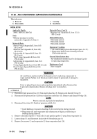
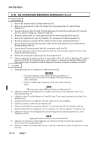
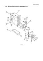
1 4 - 2 1 . E X PANSION VA LVE REPLACEMENT
This task covers:
a.
Removal
b.
Installation
INITIAL SETUP:
Applicable Models
_______________
M997, M997A1, M997A2
To o l s
____
General mechanic's tool kit:
automotive (Appendix G, Item 1)
M a t e r i a l s / P a rt s
_____________
Moisture seal (Appendix E, Item 152) (R-12 only)
Three O-rings (Appendix E, Item 105) (R-12 only)
Lubricating oil (Appendix B, Item 35) (R-12 only)
Lubricating oil (Appendix B, Item 35.1) (FR-12 only)
O-ring (Appendix E, Item 106) (FR-12 only)
O-ring (Appendix E, Item 104.2) (FR-12 only)
Two O-rings (Appendix E, Item 105) (FR-12 only)
Moisture seal (Appendix E, Item 151.1) (FR-12 only)
Manual Refere n c e s
________________
TM 9-2320-280-20
TM 9-2320-280-24P
Equipment Condition
_________________
• Air-conditioning system discharged (para. 14-17).
• Evaporator blower housing opened
(TM 9-2320-280-20).
General Safety Instructions
______________________
Air conditioner system must be discharged prior to
replacing components.
Maintenance Level
_______________
Direct support
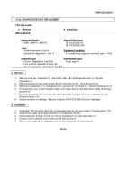
a. Removal
TM 9-2320-280-34
1 4 - 1 1 4
Change 1
WARNING
Air conditioner system must be discharged prior to replacing components in
vapor system. Failure to do this may result in injury to personnel or damage
to equipment
CAUTION
Cover or plug all open hoses and connections immediately after disconnection
to prevent contamination. Remove all plugs prior to connection.
1±
.
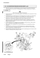
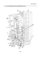
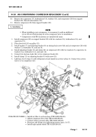
Remove moisture seal (3) from evaporator outlet tube (1). Discard moisture seal (3).
2±
.
Loosen clamp (2) and slide control tube (12) from clamp (2).
3±
.
Disconnect expansion valve pressure tube (7) from evaporator outlet tube (1) and remove O-ring (13).
Discard O-ring (13).
N±O±T±E
Perform steps 4 and 5 for FR-12 systems only.
4±
.
Remove screw (10) and clamp (8) securing sight glass tube (11) to evaporator (14).
5±
.
Disconnect and remove sight glass tube (11) and two O-rings (9) from thermo expansion valve (6) and
sight glass tube (15). Discard O-rings (9).
N±O±T±E
Perform step 6 for R-12 systems only.
6±
.
Disconnect expansion valve (6) from sight glass tube (11) and remove O-ring (9). Discard O-ring (9).
7
.
Disconnect and remove expansion valve (6) from inlet tube (4) and remove O-ring (5). Discard O-ring (±5±)±
.
b. Installation
CAUTION
• During installation of expansion valve, avoid excessive bending or kinking
of control tube and pressure tube.
• Avoid overtightening of clamp securing expansion valve control tube to
outlet tube.
Back to Top

