TM-9-2320-283-13-P - Page 65 of 400
0012-1
TM 9-2320-283-13&P
0012
FIELD MAINTENANCE
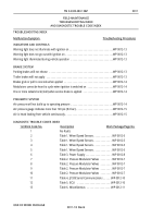
TROUBLESHOOTING PROCEDURES
References
DA-Form 2404
DA-Form 5504
DA-Form 5988-E
TM 9-2320-283-10
TM 9-2320-283-20
WP 0004
WP 0005
WP 0011
WP 0019
References–continued
WP 0020
WP 0021
WP 0022
WP 0023
WP 0028
WP 0029
WP 0030
WP 0032
WP 0034
INTRODUCTION
This work package contains Field Maintenance level troubleshooting procedures for correcting unsatisfactory
operation and basic equipment malfunctions for the M915A1 equipped with Antilock Braking System (ABS).
Field troubleshooting includes use of the ABS diagnostic modes.
Each troubleshooting procedure lists a fault symptom describing a specific problem. Under each symptom is a
list of possible malfunctions in the order of probability that may be the cause of the problem. Finally, a
corrective action is provided for each malfunction followed by work package or TM reference or instruction to
notify your supervisor.
Prior to performing any troubleshooting procedure, the following recommendations should be observed:
NOTE
This TM cannot list all possible malfunctions that may occur. If the
symptom for a particular problem or malfunction is not listed in this
work package, notify your supervisor.
1.
Isolate the component where the malfunction occurs by finding the symptom that most accurately
describes the problem.
2.
Perform troubleshooting procedures in the order in which steps are listed.
3.
Consider the possibility that the problem could be simple in origin and may require only minor
adjustment, use common sense.
4.
If a problem cannot be corrected after performing all corrective actions listed for a given symptom,
notify your supervisor.
5.
If the corrective action is not authorized at the Field Maintenance level, maintainers should provide a
brief written description of the problem using an Equipment Inspection and Maintenance Worksheet,
DA-Form 2404 or DA-Form 5988-E, and Maintenance Request Form, DA-Form 5504.
HOW TO USE ABS DIAGNOSTICS
The M915A1 ABS Electronic Control Unit (ECU) contains self-testing diagnostic circuitry that continuously
monitors the operation of the ABS. The ABS diagnostics can be accessed in two ways: the blink code switch or
by plugging in a hand-held or PC based diagnostic tool into the ECU diagnostic connector. When a fault in the
ABS is detected by the ECU, the ECU will automatically control the following:
Illuminate the ABS warning light. Refer to WP 0004.
Partially or fully disable the ABS depending on the malfunction.
Record the trouble code information in the ECU's memory.
INITIAL SETUP:
Back to Top


