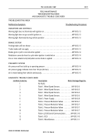
TM-9-2320-283-13-P - Page 72 of 400
TM 9-2320-283-13&P
0012
0012-8
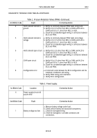
Table 3. Power Supply.
Table 2. Pressure Modulator Valves (PMV)
–Continued
.
2nd Blink Code
Fault
Corrective Action
4
Hold solenoid shorted to
ground
a. Verify no continuity between PMV leads and ground.
b. Verify 4.9 to 5.5 ohms from REL to CMN and HLD to
CMN and 9.8 to 11 ohms from REL to HLD.
c. Check for corroded/damaged wiring or connectors between
ECU and PMV.
5
Hold solenoid shorted to
voltage
a. Verify no continuity between PMV leads and voltage.
b. Verify 4.9 to 5.5 ohms from REL to CMN and HLD to
CMN and 9.8 to 11 ohms from REL to HLD.
c. Check for corroded/damaged wiring or connectors between
ECU and PMV.
6
Hold solenoid open circuit
a. Verify 4.9 to 5.5 ohms from REL to CMN and HLD to
CMN and 9.8 to 11 ohms from REL to HLD.
b. Check for corroded/damaged wiring or connectors between
ECU and PMV.
7
CMN open circuit
a. Verify 4.9 to 5.5 ohms from REL to CMN and HLD to
CMN and 9.8 to 11 ohms from REL to HLD.
b. Check for corroded/damaged wiring or connectors between
ECU and PMV.
8
Configuration error
a. A mismatch exists between the ECU configuration and the
modulator installation and wiring.
b. Verify PMV wiring and installation.
c. Verify ECU configuration.
1st Blink Code
Location
Corrective Action
6
Power supply (circuit 40
purple wire)
2nd Blink Code
Fault
Corrective Action
1
Battery voltage too low
a. Measure battery voltage under load.
b. Check vehicle battery and associated components.
c. Check for damaged wiring.
d. Check for damaged or corroded connectors and
connections.
DIAGNOSTIC TROUBLE CODE TABLES–CONTINUED
Back to Top


