TM-9-2320-283-13-P - Page 69 of 400
TM 9-2320-283-13&P
0012
0012-5
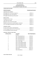
CHANGING DIAGNOSTIC MODES–CONTINUED
Dynamometer Test Mode
–This mode is used to disable the Automatic Traction Control (ATC); the ABS for the
M915A1 does not include ATC.
Reconfigure ECU Mode
–This mode is used when replacing the ECU to verify the new unit has the correct
default settings. The correct ECU for the M915A1 ABS is programmed and configured by part number. To
access this mode, the test switch is pressed and held in prior to switching the vehicle ignition to ON position.
Once power is on, the test switch is released and then pressed seven times to enter the Reconfiguration ECU
Mode.
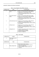
DIAGNOSTIC TROUBLE CODE TABLES
Table 1. Wheel Speed Sensors.
1st Blink Code
Location
Corrective Action
2
3
4
5
Left steering axle wheel
sensor
Right steering axle wheel
sensor
Left drive axle wheel
sensor
Right drive axle wheel
sensor
2nd Blink Code
Fault
Corrective Action
1
Excessive air gap
a. Adjust sensor to contact tone ring. Refer to WP 0022.
b. Rotate wheel and verify a minimum of 0.25 VAC sensor
output at 0.5 Revolutions Per Second (RPS).
c. Verify condition of sensor head.
d. Verify mounting of tone ring and condition of slots. Refer to
WP 0021.
e. Verify proper bearing end play. Refer to WP 0019.
f. Verify condition and tension of clamp sleeve. Refer to
WP 0019.
g. Verify sensor clamping and cable routing. Refer to WP 0022.
2
Output low at drive-off
a. Adjust sensor to contact tone ring. Refer to WP 0022.
b. Rotate wheel and verify a minimum of 0.25 VAC sensor
output at 0.5 RPS.
c. Verify condition of sensor head.
d. Verify mounting of tone ring and condition of slots. Refer to
WP 0021.
e. Verify proper bearing end play. Refer to WP 0019.
f. Verify condition and tension of clamp sleeve. Refer to
WP 0019.
g. Verify sensor clamping and cable routing. Refer to
WP 0022.
Back to Top


