TM-9-2320-283-20-2 - Page 654 of 852
TM 9-2320-283-20-2
BRAKE SYSTEM.
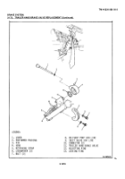
3-174. BRAKE TREADLE VALVE REPLACEMENT (Continued).
LOCATION/ITEM
ACTION
REMARKS
C.
INSTALLATION (Continued)
26 Three screws (13)
Install in item (15) and
and lockwashers
tighten.
(12).
27 Nut (9)
Install onto item (10)
Item (9) should be in-
stalled to the height
measured in step 21
during disassembly.
28 Stop button (10)
Install into item (15) until
and nut (9)
item (9) seats against item
(15).
Tighten item (9)
against item (15).
29 Brake valve (20)
Line up holes in item (20)
An assistant will be
with item (33)
required to hold item
(20) onto item (33).
30 Three screws (4),
Install into item (20) and
lockwashers (5),
tighten.
and washers (6).
NOTE
Wrap
all
pipe
threads
with
thread sealing tape prior to installation.
31 Reducer (32) and
Install in item (20)
Install items (1), (29),
three elbows (1),
and (30) according to
(29), and (30)
the alining marks made
during disassembly.
32 Tube (28)
Install onto item (29).
33 Tube (31)
Install onto item (30).
34 Plug (3)
Install in item (20).
35 Two plugs (7)
Install in item (20) on right-
hand side.
36 Three plugs (2)
Install in item (20) on left-
hand side
3-1026
Back to Top


