TM-9-2320-285-24-1 - Page 16 of 987
TM 9-2320-285-24-1
1-17.
FUEL SYSTEM (CONT)
3.
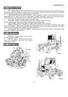
AIR CLEANER AND RESTRICTION INDICATOR.
Air cleaner traps dust and dirt from air and sends filtered air to
turbocharger; restriction indicator, mounted on right instrument panel, monitors resistance to air flow due to trapped
particles and displays red band when preset restriction level is reached.
4.
TURBOCHARGER AND BLOWER ASSEMBLY.
Blower assembly, mounted on top of engine block, uses two
double-lobed rotors to deliver fresh air from turbocharger to engine; turbocharger, driven by engine exhaust gases,
delivers amount of air that engine requires for combustion, determined by amount of engine exhaust.
5.
FUEL TANK.
50 gallon capacity; mounted on left side of frame.
6.
GOVERNOR.
Mechanical, limiting-speed type governor, mounted on flywheel housing
of engine, controls engine-idle speed and limits maximum engine operating speed.
7.
FUEL FILTERS.
Primary and secondary fuel filters remove impurities from fuel system.
8.
ENGINE STARTING AID.
Includes quick start switch, ether cylinder, ether solenoid, and tubing; aids engine
starting in cold weather.
When switch is operated, electrically-operated solenoid valve injects pre-measured shot of highly
volatile ether into air intake system.
Replaceable cylinder supplies ether.
9.
ACCELERATOR AND THROTTLE LINKAGE.
Controls engine speed through operation of accelerator pedal
transmitted by linkage to engine governor.
1-18.
EXHAUST SYSTEM
1.
MUFFLER.
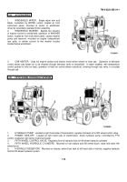
Muffles engine noise; mounted
vertically at right side of vehicle.
2.
EXHAUST PIPES.
Channel engine exhaust
smoke and combustion by-products from engine
turbocharger to muffler.
1-19.
COOLING SYSTEM
1-7
Back to Top

