TM-9-2320-285-24-1 - Page 17 of 987
TM 9-2320-285-24-1
1-19.
COOLING SYSTEM (CONT)
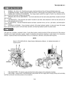
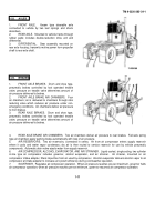
1.
RADIATOR.
Mounted at front of vehicle; cools engine coolant.
Includes coolant
recovery system.
Bottom tank contains transmission cooler which cools transmission fluid.
2.
RADIATOR SHROUD.
Positioned around radiator; increases radiator cooling efficiency.
3.
THERMOSTATS.
Thermostats in water manifold aid quick engine warm-up by diverting coolant from radiator until
coolant reaches a temperature of 170 degrees F.
4.
COOLANT FILTER.
Removes impurities from circulating coolant.
5.
WATER PUMP.
Driven by matched set of V-belts from engine camshaft pulley.
6.
FAN.
Mounted on fan clutch assembly at front of engine.
7.
FAN CLUTCH ASSEMBLY.
On-off type pneumatic clutch; controls engine temperature by turning fan on and off;
pneumatically connected to solenoid.
Solenoid is electrically connected to thermal switch.
1-20.
ELECTRICAL SYSTEM
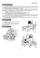
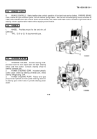
1.
ALTERNATOR AND BELT.
Engine-driven by
matched set of V-belts; 90 ampere alternator charges
batteries and supplies current for vehicle electrical
circuits.
2.
STARTER.
Enclosed shift-type-lever starter
motor; operated by solenoid mounted on starter.
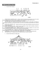
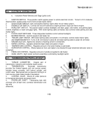
3.
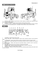
INSTRUMENT PANELS.
Refer to para 1-20a
and 1-20b below for descriptions of indicators, lights, and
switches mounted on instrument panels.
4.
SWITCHES,
TURN
SIGNAL,
ENGINE
WARNING KIT, AND WATER LEVEL WARNING KIT.
Switches include neutral start switch, back-up light
switch, and service brakes and trailer hand brake stop
light switches.
Turn signal control lever operates
steering column-mounted turn signal switch.
Engine
warning kit includes engine-mounted alarmstat sensor
and oil pressure warning sensor.
Water level warning kit
includes engine-mounted
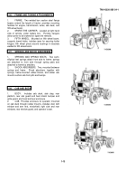
5.
LIGHTS.
Mounted at front of vehicle are two headlights, two front turn indicator lights, and marker lights.
Mounted
at vehicle rear are two tail and stop lights.
Floodlights are mounted at left and right cab roof and on rear cab guard.
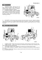
6.
SENDING UNITS.
Includes fuel level sender, water temperature sender, oil pressure sender, and transmission
temperature sender.
7.
HORN AND SWITCH.
Horn switch, operated by steering wheel horn button, sounds electric horn.
Horn is
mounted at front frame crossmember.
8.
BATTERIES.
Four 12 Volt wet-cell batteries in parallel supply vehicle operating voltage.
9.
WIRING HARNESSES.
Eight wiring harnesses supply current to vehicle electrical components.
Fuse block,
located at cab interior, right hand side, provides circuit protection.
1-8
Back to Top

