TM-9-2320-328-13-P-1 - Page 1173 of 1318
TM 9-2320-328-13&P-1
0106-5
DRAFT
0106
Change 1
.
HWT0821
.
Step 6.
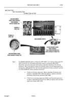
Install circuit breaker FS 4 (WP 0242).
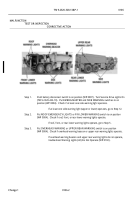
Remove cab instrument panel C (WP 0205).
Push battery disconnect switch to on position (WP 0007).
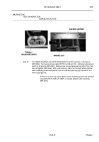
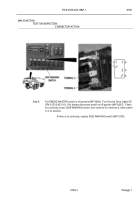
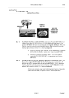
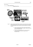
Disconnect cab instrument
panel wire harness SIDE WARNING switch connector.
Turn Service Drive Lights On
(TM 9-2320-422-10).
Put EMERG MASTER switch to on position (WP 0004).
With a
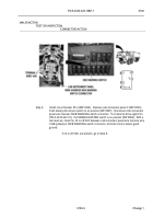
test lead set, check for 22 to 28 VDC between cab instrument panel wire harness wire
1648 (yellow) at SIDE WARNING switch connector, terminal 6 and a known good
ground.
.
If 22 to 28 VDC are present, go to Step 8.
.
MALFUNCTION
TEST OR INSPECTION
CORRECTIVE ACTION
Back to Top


