TM-9-2320-328-13-P-1 - Page 150 of 1318
TM 9-2320-328-13&P-1
0017-20
DRAFT
0017
b.
Applicable Documents.
1.
Document and Specification Precedence.
The following documents and/or publications form a part of this design specification as specified herein.
In the event of conflict between the requirements of this design specification and referenced documents,
the referenced specifications shall take precedence.
Federal Government - National Fire Protection Agency:
(a)
NFPA 414 (2001)
Standard for Aircraft Rescue and Fire-Fighting Vehicles (Quincy, MA)
(b)
NFPA 1901 (2003)
Standard for Automotive Fire Apparatus (Quincy, MA)
2.
Electro-Mechanical Requirements.
The HEWATT pump panel display shall be capable of reading a transducer signal and driving a pump
displacement solenoid.
Various inputs and outputs will allow the system to perform independent or
dependent operations based on user input.
c.
Software Operation Requirements.
1.
System Initiation Requirements.
The HEWATT pump panel display will be powered from the battery disconnect switch located in the
driver’s area.
The HEWATT pump panel display will initialize confirming all internal operations are
operating properly and the controller ECU is receiving proper engine and transmission data.
If issues
are found during the initial power up sequence, system errors or warnings will be logged and the
appropriate indicator lights will be activated on the Home screen.
If no issues are found during the
initialization process, no errors or warnings will be displayed and the system will continue to the Home
screen.
2.
Software Operation.
NOTE
Pressure governor display may take up to 20 minutes to operate in cold climate
conditions.
(a)
Home Screen.
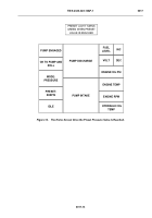
The Home screen for the HEWATT pump panel display shall look like Figure 21.
Once the display is powered and initialization has finished, the display shall advance to the Home
screen.
The user will begin interfacing with the display from this screen. User options from this
screen shall include:
Indicator lights on the Home screen include:
•
Mode selection
•
Preset selection
•
Idle selection
•
Increase selection
•
Decrease selection
•
Menu selection
•
Pump Engaged light
•
Throttle Ready light
Back to Top


