TM-9-2320-328-13-P-1 - Page 996 of 1318
TM 9-2320-328-13&P-1
0089-8
DRAFT
0089
Change 1
.
.
.
.
.
.
.
.
.
.
.
.
.
.
.
.
.
.
.
.
.
.
.
.
.
.
HWT3227
.
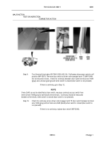
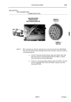
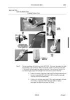
Step 14.
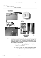
Turn Service Drive Lights Off (TM 9-2320-422-10).
Pull battery disconnect switch to off
position (WP 0007).
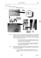
Remove door switch at driver side rear stowage compartment
D1 (WP 0246).
Do not disconnect wires.
Check for continuity between door switch
terminal wire 1609 (gray) and a known good ground when switch is closed (door switch
is not pressed).
.
If there is continuity, repair wire 1609 in diver side body wire harness if
repairable (TM 9-2320-325-14&P), or replace driver side body wire
harness (WP 0286).
.
NOTE
If wire 2640 can not be identified at door switch, measure continuity across switch from
terminal wire 1609 (gray) to both black wire terminals.
Continuity should be measured
between all terminals, when switch is closed (door switch is not pressed).
.
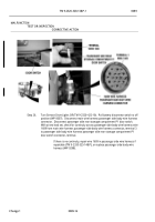
Step 15.
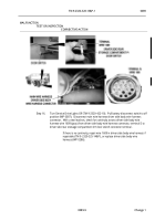
Check for continuity across driver side rear stowage compartment D1 door switch
between terminal wire 1609 (gray) and terminal wire 2640 (black) when switch is closed
(door switch is not pressed).
.
a.
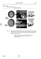
If there is continuity, repair wire 2640 in driver side wire harness if
repairable (TM 9-2320-325-14&P), or replace driver side body wire
harness (WP 0286).
.
b.
If there is no continuity, replace door switch (WP 0246).
.
MALFUNCTION
TEST OR INSPECTION
CORRECTIVE ACTION
Back to Top

