TM-9-2320-328-13-P-2 - Page 1129 of 1390
TM 9-2320-328-13&P-2
0293-1
DRAFT
0293
FIELD LEVEL MAINTENANCE
NO. 1 DRIVER SIDE FLOW SENSOR WIRE HARNESS REPLACEMENT
INITIAL SETUP:
REMOVAL
-
-
-
-
-
-
-
-
-
-
-
-
-
-
-
-
-
-
-
-
-
-
-
-
-
-
-
-
-
-
-
-
-
-
-
-
-
NOTE
•
Note routing of No. 1 driver side flow sensor wire harness prior to removal to ensure
proper installation.
•
No. 1 driver side flow sensor wire harness is routed from pump house to pump operator’s
panel assembly.
•
Note position and remove split loom, cushion clips, and cable ties as required.
•
Tag and mark connectors prior to removal to ensure proper installation.
1.
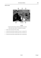
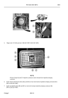
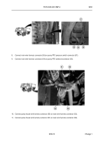
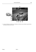
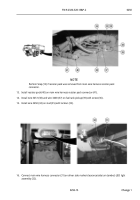
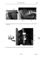
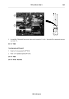
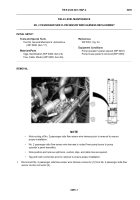
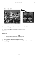
Disconnect No. 1 driver side flow sensor wire harness connector (1) from No. 1 driver side flow sensor valve
control connector (2).
-
-
-
-
-
-
-
-
-
-
-
-
-
-
-
-
-
-
-
-
-
-
-
-
-
-
-
-
-
-
-
-
-
-
-
-
-
HWT1940
Tools and Special Tools
Tool Kit, General Mechanic’s: Automotive
(WP 0398, Item 17)
Materials/Parts
Tags, Identification (WP 0400, Item 23)
Ties, Cable, Plastic (WP 0400, Item 26)
References
WP 0391, Fig. 34
Equipment Conditions
Pump operator’s panel opened (WP 0207)
Pump house panel E removed (WP 0339)
Pump house access door opened (WP 0008)
Back to Top

