TM-9-2320-328-13-P-2 - Page 1141 of 1390
TM 9-2320-328-13&P-2
0296-1
DRAFT
0296
FIELD LEVEL MAINTENANCE
PASSENGER SIDE AUXILIARY INLET VALVE CONTROL WIRE HARNESS REPLACEMENT
INITIAL SETUP:
REMOVAL
-
-
-
-
-
-
-
-
-
-
-
-
-
-
-
-
-
-
-
-
-
-
-
-
-
-
-
-
-
-
-
-
-
-
-
-
-
NOTE
•
Note routing of passenger side auxiliary inlet valve control wire harness prior to removal to
ensure proper installation.
•
Passenger side auxiliary inlet valve control wire harness is routed from pump house to
pump operator’s panel assembly.
•
Note position and remove split loom, cushion clips, and cable ties as required.
•
Tag and mark connectors prior to removal to ensure proper installation.
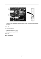
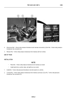
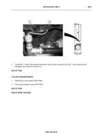
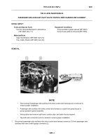
1.
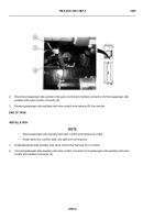
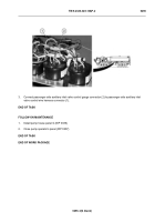
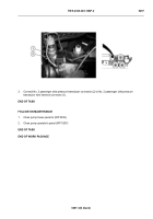
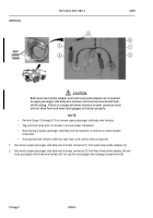
Disconnect passenger side auxiliary inlet valve control wire harness connector (1) from passenger side
auxiliary inlet valve control gauge connector (2).
-
-
-
-
-
-
-
-
-
-
-
-
-
-
-
-
-
-
-
-
-
-
-
-
-
-
-
-
-
-
-
-
-
-
-
-
-
HWT2309
Tools and Special Tools
Tool Kit, General Mechanic’s: Automotive
(WP 0398, Item 17)
Materials/Parts
Tags, Identification (WP 0400, Item 23)
Ties, Cable, Plastic (WP 0400, Item 26)
Equipment Conditions
Pump operator’s panel opened (WP 0207)
Pump house panel G removed (WP 0339)
Back to Top

